Hackaday.io is having a 2024 Business Card Contest between May and July 2024, I decided to enter the contest with my own design. This describes my design process from planning to the completion for a business card that can be used as real time clock with 3-year battery life and can also be used as an ATtiny3227 development board.
Two years ago, I designed an NTP clock powered by an ESP-12 (ESP8266) module and recently further improve it to extend the battery life from 45-days to 160-days, powered by a 1000-mAh LiPo battery.
I’ve been using Modern AVR chip (i.e. ATtiny 0-2 series, ATmega 0-series, and AVR Dx series) since its launch and like it very much for its easy to program, better feature sets and functionality, lower power consumption, and more memory than the Classes AVR chips (such as ATmega328), I created my own ATtiny3217 development board 4 years ago.
This project is a combination of the two projects, by replacing the power-hungry ESP-12 with an ATtiny3227, with PCB of a credit card size, and the thickness of only 3.2mm (1mm PCB, plus the battery holder of a CR2016 of 2.2mm).
Planned Features
- Business with contact information and QRCode for website.
- Credit card size of 85.5x54mm.
- 3.2mm thickness including 1mm PCB.
- It is a clock/watch with 12 Charlieplexing LEDs.
- It is a ATtiny3227 development board with all the pins (22-GPIO pins) break-out.
- Programmable with megaTinyCore as an Arduino or with bare metal with just VSCode and avrdude.
- Powered by a 98mAh CR2016 coin cell battery.
- Designed for low-power, with design target of 1-2uA during sleep, and 2.5mA when time is showed.
- Battery life of 2.6 years if pressed the button to view the time 24 times a day.
- Cheap to produce, BOM cost of $8 based on sourcing from Digikey and much less if sourced from LCSC.
![]()
The PCB fabrication is sponsored by PCBWay. If you never used PCBWay services before, consider to give it a try. PCBWay provides services from PCB fabrication, assembly to CNC and 3D printing services with very reasonable price and fast turn-around time. Visit PCBWay for a quick quote for up to 10 pieces of PCB at as low as $5.00.
Hardware
The schematic is quite similar to my NTP Clock project, consists of 12-LED with charlieplexing, minus the charging circuit, and replace the power hungry ESP8266 with an ATtiny3227 tinyAVR 2-series MCU, with all the pins break-out.
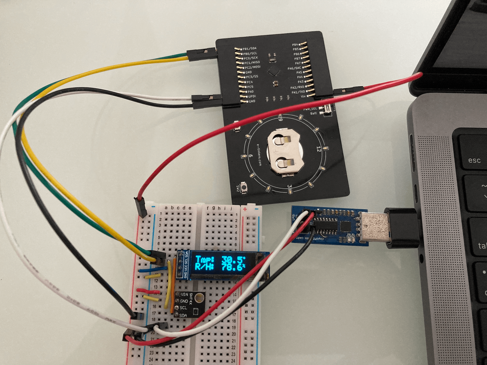
I setup a test environment which consists of an ATtiny3227 development board, and external 32.768kHz crystal oscillator, and 12 LEDS (I don't have sufficient red LEDs, so the test setup consists of 6 red LEDs and 6 green LEDs).
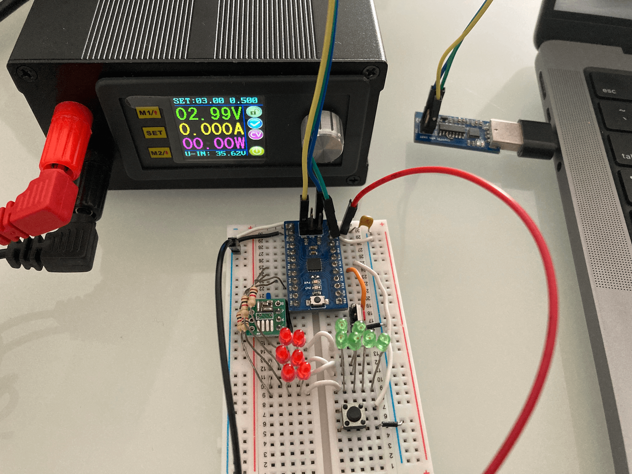
I will further explain the hardware design later whenever appropriate when discussing any design considerations. For now, I will talk about the BOM cost and the ATtiny3227 Power Down Mode and the tests that I have done in order to determine the battery life for the Business Card.
BOM
The BOM cost is calculated based on sourcing from DigiKey since they are the sponsor of the 2024 Business Card Challenge contest, with the exception of a couple of components. The SPDT switch and the CR2016 battery holder are based on the components that I already have that were sourced from LCSC, similar part can be found in DigiKey but the footprint might not be 100% align with the part that I have. Two SMD 1x12 Connector Female Socket are also based on LCSC price as I can't find the identical part from DigiKey. Maybe I didn't find harder enough. The total BOM cost is around \$8 including CR2016 as well as an estimated PCB fabrication cost/piece. The cost of PCB is based on PCBWay's fabrication costs of \$5 for 10 pcs, so each piece is at \$0.5 and used as the BOM cost.
ATtiny3227 Power Down Mode
Before creating PCB or writing software, it is important to understand the power consumption of the circuitry at both active mode and sleep mode, and confirm some of the assumptions that I made in battery life as I planned to use CR2016 which only has the capacity of 98mAh. The bigger battery CR2032 would have a bigger capacity of 235mAh, but the thickness increased. I want to have the business card with slim profile, CR2016 with the battery holder will have a thickness of 2.2mm as compare to the CR2032 one of 3.6mm, without including the PCB thickness which will add another 1mm.
The first thing I did is to determine the system clock speed that I should used for the design. For Modern AVR chips (Refer to ATtiny 0, 1 and 2-series, ATmega 0-series, and AVR Dx series), all clocks are active in active mode, and the CPU is running. Power consumption in active mode is proportional to the operating frequency of the system clock. As the charlieplexing clock does not demand high-frequency operation, and therefore can benefit from lowering the system clock.
The ATtiny3227 (this applies to the entire ATtiny 0, 1 and 2-series) can operate at 20MHz with a Low-Power internal oscillator without the need for external crystal. This oscillator can operate at multiple frequencies, selected by the value of the Frequency Select bits (FREQSEL) in the Oscillator Configuration Fuse (FUSE.OSCCFG). So I configure the clock to run at 20MHz, 10MHz and 5MHz and write a simple program to test the current consumption at ative mode.
In order to simulate the actual usage of the actual application, I config the RTC to wake up on every second to increment the timeCount which is going to be used for keeping the time in seconds. In order to make sure that the configuration of the RTC work as expected, I initially also config the PORTA PIN7 (which has an LED attached to it on the ATtiny3227 development board) so that it will toggle the LED on every wake-up, once I know the RTC is working, I then comment out the PORTA configuration so that I can measure the current without LED blinking.
#include <avr/io.h>
#include <avr/interrupt.h>

volatile uint32_t timeCount = 0;

ISR (RTC_PIT_vect) {
  timeCount = (timeCount + 1) % 43200; // count up to 12-hour (12 * 3600) = 43200
  // PORTA.OUTTGL = PIN7_bm;
  RTC.PITINTFLAGS = RTC_PI_bm;         // Clear periodic interrupt flag
}

void configRTC() {

  /* Using external 32.768kHz clock on PB2 and PB3 */
  _PROTECTED_WRITE(CLKCTRL.XOSC32KCTRLA, CLKCTRL_RUNSTDBY_bm | CLKCTRL_ENABLE_bm);
  while (RTC.STATUS > 0);
  RTC.CLKSEL = RTC_CLKSEL_TOSC32K_gc;                   // clock from  XOSC32K (PB2 & PB3) or TSOC1 pin (PB3)

  RTC.PITCTRLA = RTC_PERIOD_CYC32768_gc | RTC_PITEN_bm; // RTC clock cycles between each interrupt
  RTC.PITINTCTRL = RTC_PI_bm;

}

int main() {

    _PROTECTED_WRITE(CLKCTRL_MCLKCTRLB, (CLKCTRL_PEN_bm | CLKCTRL_PDIV_4X_gc)); // running at 20/4 = 5MHz

    // PORTA.DIRSET = PIN7_bm;

    configRTC();

    sei();

    while(1) {

    }

    return 0;

}
Here is the result of current consumptions for various operating voltages at different clock speeds. Current consumption at 2V is measured because at 2V the CR2016 battery is likely running out of power even though the ATtiny3227 is capable operate at 1.8v.
| Operating Voltage | 20MHz | 10MHz | 5MHz |
|---|---|---|---|
| 5V | 10.5mA | 6.1mA | 3.7mA |
| 3V | 4mA | 3.1mA | 1.8mA |
| 2V | 2.47mA | 1.4mA | 1.2mA |
These values are taken when the LED is off, I further test the battery consumption at 3V operation running at 5MHz clock speed, the current consumption when the LED on is 2.35mA. The LED is connect to between the GPIO pin and GND via a 2k-ohm resistor. The published current consumption on ATtiny3227 datasheet for the same operation condition is showing as 2mA typical so the measurement is inline with the datasheet.
The table shows that the operating voltage affects the power consumption greatly. The Business Card design should definitely set to operate at 5MHz instead of 20MHz.
In additonal to the 20MHz main clock, there is another 32.768kHz internal clock for RTC (Real-Time Counter). The 32.768kHz oscillator is optimized for Ultra Low-Power (ULP) operation. "Power consumption is decreased at the cost of decreased accuracy compared to an external crystal oscillator" as per Microchip Application Note. Since the Business Card is a real-time Clock/watch, Ideally I'd want to have an accurate 32,768kHz clock base than the internal "decreased accuracy" clock. So I solder an Seiko Epson 32.768kHz 20ppm crystal together with two 18pF capacitor to a break-out board and connected to the TOSC1 and TOSC2 pins of the ATtiny3227, and program the ATtiny3227 to use either the internal oscillator or the external crystal, I modified the code slightly to configure the ATtiny3227 to use either the Internal Oscillator or the external crystal clock with a macro USE_INTERNAL_OSC.
#define USE_INTERNAL_OSC

void configRTC() {

#if defined(USE_INTERNAL_OSC)
  /* Using ULP internal 32.768kHz clcok */
  while (RTC.STATUS > 0);
  RTC.CLKSEL = RTC_CLKSEL_INT32K_gc;                    // 32.768kHz Internal Oscillator
#else
  /* Using external 32.768kHz clock on PB2 and PB3 */
  _PROTECTED_WRITE(CLKCTRL.XOSC32KCTRLA, CLKCTRL_RUNSTDBY_bm | CLKCTRL_ENABLE_bm);
  while (RTC.STATUS > 0);
  RTC.CLKSEL = RTC_CLKSEL_TOSC32K_gc;                   // clock from  XOSC32K (PB2 & PB3) or TSOC1 pin (PB3)
#endif

  RTC.PITCTRLA = RTC_PERIOD_CYC32768_gc | RTC_PITEN_bm; // RTC clock cycles between each interrupt
  RTC.PITINTCTRL = RTC_PI_bm;

}
I don't see any noticable difference in current consumption between using the internal oscillator and using the external crystal as the Seiko Epson part that I picked has very low driving power of 0.5uW. So this is a good news and answered one of my questions in selecting the crystal and external RTC clock.
The next test is to evaluate the sleep mode performance of ATtiny3227. ATtiny3227 has three different sleep modes.
- Idle: The CPU stops executing code, resulting in reduced power consumption. All peripherals are running, and all interrupt sources can wake the device.
- Standby: All high-frequency clocks are stopped apart from any peripheral or clock that are enabled to run in Standby sleep mode. A subset of interrupt sources can wake the device.
- Power Down: All high-frequency clocks are stopped, only the PIT functionality(as part of RTC) is available, plus a few interrupt sources can wake the device.
I extend the code to configure the Power Down mode to operate at 5MHz main clock speed, the current consumption during the Power Down sleep mode is 88uA, this is way much higher than what is showing on the datasheet Table 33-5 (Power Consumption in Active, Idle, Power-Down, Standby and Reset Mode) of 1uA! So what is going on?
int main() {

    _PROTECTED_WRITE(CLKCTRL_MCLKCTRLB, (CLKCTRL_PEN_bm | CLKCTRL_PDIV_4X_gc)); // running at 20/4 = 5MHz

    // PORTA.DIRSET = PIN7_bm;

    configRTC();

    SLPCTRL.CTRLA = SLPCTRL_SMODE_PDOWN_gc;  // config sleep controller powerdown mode

    sei();

    while(1) {
      SLPCTRL.CTRLA |= SLPCTRL_SEN_bm;  // sleep enable, this is equivalent to sleep_enable()
      __asm("sleep");                   // this is equivalent to sleep_cpu()
      SLPCTRL.CTRLA &= ~SLPCTRL_SEN_bm; // sleep disable , this is equivalent to sleep_disable()
    }

    return 0;

}
According to Microchip Application Note AN2515 AVR Low Power Techniques, it suggests to reset all the unused pins (i.e. set it to input), and enabled the internal pull-up resistor on each pin. So I modified the code to config each of the GPIO pin like so before enabling the sleep mode:
    PORTA.OUTCLR = PIN0_bm;             // clear PORTA, PIN0
    PORTA.PIN0CTRL = PORT_PULLUPEN_bm;  // enable PULLUP
The current consumption drop to 56uA from previous 88uA, still not near to the 1uA?!
Microchip application note also mentioned "In addition, disabling the digital input buffer on unused pins will further lower the power consumption." without much explanation. So I modified the code again to disable the input buffer and kept the pull-up enabled:
    PORTA.OUTCLR = PIN0_bm;                                         // clear PORTA, PIN0
    PORTA.PIN0CTRL = PORT_PULLUPEN_bm | PORT_ISC_INPUT_DISABLE_gc;  // enable PULLUP and disable the input buffer
The current drop from 56uA to 36uA, hmm... it looks like disable the input buffer does has the effect of reducing the current consumption, so maybe the 36uA was the leakage due to the pull-up resistors? I decided to give it a try to just disable the input buffer without the pull-up.
    PORTA.OUTCLR = PIN0_bm;                      // clear PORTA, PIN0
    PORTA.PIN0CTRL = PORT_ISC_INPUT_DISABLE_gc;  // disable the input buffer
Bingo! It shows a current consumption of 1uA at Power Down mode! So to summarize all the tests that I've done:
| Power Down Mode | Current @3v/5MHz |
|---|---|
| With only Power Down setup | 88uA |
| With all pins set to INPUT and enable PULL-UP | 56uA |
| With all pins set to INPUT and PULL-UP + disable input buffer | 36uA |
| With all pins set to INPUT and disable input buffer | 1uA |
and the final test code that I used:
void turnOffAllPins() {
  // set all pin to input
  PORTA.DIRCLR = PIN0_bm | PIN1_bm | PIN2_bm | PIN3_bm | PIN4_bm | PIN5_bm | PIN6_bm | PIN7_bm;
  PORTB.DIRCLR = PIN0_bm | PIN1_bm | PIN2_bm | PIN3_bm | PIN4_bm | PIN5_bm | PIN6_bm | PIN7_bm;
  PORTC.DIRCLR = PIN0_bm | PIN1_bm | PIN2_bm | PIN3_bm | PIN4_bm | PIN5_bm;

  // disable input buffer to lower power consumption in sleep mode
  PORTA.PIN0CTRL = PORT_ISC_INPUT_DISABLE_gc;
  PORTA.PIN1CTRL = PORT_ISC_INPUT_DISABLE_gc;
  PORTA.PIN2CTRL = PORT_ISC_INPUT_DISABLE_gc;
  PORTA.PIN3CTRL = PORT_ISC_INPUT_DISABLE_gc;
  PORTA.PIN4CTRL = PORT_ISC_INPUT_DISABLE_gc;
  PORTA.PIN5CTRL = PORT_ISC_INPUT_DISABLE_gc;
  PORTA.PIN6CTRL = PORT_ISC_INPUT_DISABLE_gc;
  PORTA.PIN7CTRL = PORT_ISC_INPUT_DISABLE_gc;

  PORTB.PIN0CTRL = PORT_ISC_INPUT_DISABLE_gc;
  PORTB.PIN1CTRL = PORT_ISC_INPUT_DISABLE_gc;
  PORTB.PIN2CTRL = PORT_ISC_INPUT_DISABLE_gc;
  PORTB.PIN3CTRL = PORT_ISC_INPUT_DISABLE_gc;
  PORTB.PIN4CTRL = PORT_ISC_INPUT_DISABLE_gc;
  PORTB.PIN5CTRL = PORT_ISC_INPUT_DISABLE_gc;
  PORTB.PIN6CTRL = PORT_ISC_INPUT_DISABLE_gc;
  PORTB.PIN7CTRL = PORT_ISC_INPUT_DISABLE_gc;

  PORTC.PIN0CTRL = PORT_ISC_INPUT_DISABLE_gc;
  PORTC.PIN1CTRL = PORT_ISC_INPUT_DISABLE_gc;
  PORTC.PIN2CTRL = PORT_ISC_INPUT_DISABLE_gc;
  PORTC.PIN3CTRL = PORT_ISC_INPUT_DISABLE_gc;
  PORTC.PIN4CTRL = PORT_ISC_INPUT_DISABLE_gc;
  PORTC.PIN5CTRL = PORT_ISC_INPUT_DISABLE_gc;

}

int main() {

    _PROTECTED_WRITE(CLKCTRL_MCLKCTRLB, (CLKCTRL_PEN_bm | CLKCTRL_PDIV_4X_gc)); // running at 20/4 = 5MHz

    SLPCTRL.CTRLA = SLPCTRL_SMODE_PDOWN_gc;  // config sleep controller powerdown mode

    // PORTA.DIRSET = PIN7_bm;

    configRTC();

    sei();

    while(1) {
      turnOffAllPins();
      SLPCTRL.CTRLA |= SLPCTRL_SEN_bm;  // sleep enable, this is equivalent to sleep_enable()
      __asm("sleep");                   // this is equivalent to sleep_cpu()
      SLPCTRL.CTRLA &= ~SLPCTRL_SEN_bm; // sleep disable , this is equivalent to sleep_disable()
    }

    return 0;

}
Battery Life Calculation
Based on the tests, I can now calculate the battery life based on a CR2016 coin cell battery which has a capacity of 98mAh.
Assuming each time when I pressed the button to show the time, the ATtiny3227 would wake up to display the time for 5 seconds, then go into Power Down sleep mode, if I check time 24 times a day during my working/awake hours (that would equivalent to the ATtiny3227 wake-up once in every hour), and we know that the power consumption with an LED on is 2.35mA (I would use 2.5mA for calculation, just to give it some margin), the total energy consumption in active mode would be (5 sec x 24 ) / 3600 = 0.03333s hours, or 25 * 0.03333s = 0.08333smAh. The energy consumption during Power Down sleep based on 1.7uA (again, give it some margin instead of using 1uA), it would be 0.0000017 x (24 - 0.033333) = 0.00004mAh, so the total would be 0.083337mAh. With the battery capacity of 98mAh, what this means is that the battery will last for 98 / 0.083337 = 1175 days! or more than 3 years!
This is better than I originally estimated, I did a few calculations to see what will be the battery life at different wake-up frequency, here is the high level summary:
| Show Time Frequency | Battery Life(days) |
|---|---|
| Once every hour or check time 24 times/day | 1175 |
| Show time once per minute | 19.6 |
| Show time once per every 5 minutes | 98 |
| Show time once per every 15 minutes | 293 |
I am ready to create the PCB and send to PCBWay for fabiration.
Software
While waiting for the PCB, it is time to write some actual code for the clock.
As I've explained the ATtiny3227 Power Down mode and the configuration of RTC, so I won't explain it again, I will focus on the rest of the design.
Charlieplexing
Charlieplexing is a multiplexing technique that able to drive n2 - n LEDs with only n GPIO pins, that is, only 4 GPIO pin are required to drive 42 - 4 = 12 LEDs. In the schematic, the LED assignment correspond to the postion of the LED on the clock face, LED D12 is designated as 0, and the PORTB, PIN4-7 of the ATtiny3227 are used as the driving pins for the LED matrix. Charlieplexing is also known as tristate multiplexing, at any giving time, only one LED is light-up based on the states of the driving pins, for example, in order to turn on LED D1, a positive voltage is apply to PB4 and a zero (ground) need to be asserted at PB5, PB6 and PB7 would have to be "disconnected" by putting it in tri-state/high impedence mode. For microcontroller, we could turn those pins to "input" mode which effectively put those pins in high impedence mode.
In software, this is achieved by defining an array of LED matrix, each consists of two states for pinConfig and pinState. The pinConfig represents the value on which the pin should be configured as INPUT or OUTPUT, the 'pinState' decided on whether the pin should be set to HIGH or LOW. The mux[LEDS] contains both the values of pinConfig and pinState for each LED. For example, to turn on the LED D1 as we previously mentioned, the mux[1] have a value of {0x30, 0x10} which when expands to binary would look like {B00110000, B00010000} with the MSB represents PB7 and LSB represents PB0. We only care for the upper 4-bits that represents PB7 - PB4. What this means is that for the pinConfig value of B00110000, both PB4 and PB5 would be set as OUTPUT, PB6 and PB7 would be set to INPUT. The pinState of B00010000 means that only PB4 is set to HIGH, which based on the schematic would turn on the LED D1 and the rest of the LEDs would be off. That's what the turnOnLED() function do. To turn off all the LEDs, it is simple, just set all the pins to INPUT mode with the turnOffLED().
#include <avr/io.h>
#include <avr/interrupt.h>
#include <util/delay.h>

#define LEDS                12

const uint32_t DISPLAY_TIME = 5000;  // 5000ms

// Charlieplexing configuration and state matrix
typedef struct {
  uint8_t pinConfig;
  uint8_t pinState;
} Mux_t;

const Mux_t mux[LEDS] = {
  {0x90, 0x80}, // 0
  {0x30, 0x10}, // 1
  {0x30, 0x20}, // 2
  {0x60, 0x20}, // 3
  {0x60, 0x40}, // 4
  {0xc0, 0x40}, // 5
  {0xc0, 0x80}, // 6
  {0x50, 0x10}, // 7
  {0x50, 0x40}, // 8
  {0xA0, 0x20}, // 9
  {0xA0, 0x80}, // 10
  {0x90, 0x10}  // 11
};

void turnOnLED(uint8_t led) {

  // enable input buffer
  PORTB.PIN4CTRL = 0;
  PORTB.PIN5CTRL = 0;
  PORTB.PIN6CTRL = 0;
  PORTB.PIN7CTRL = 0;

  // rest all pins to input and set it to low
  PORTB.DIRCLR = (PIN4_bm | PIN5_bm | PIN6_bm | PIN7_bm);
  PORTB.OUTCLR = (PIN4_bm | PIN5_bm | PIN6_bm | PIN7_bm);

  // set pin(s) based on mux.pinConfig and mux.pinState value
  PORTB.DIRSET = mux[led].pinConfig;
  PORTB.OUTSET = mux[led].pinState;

}

int main() {

  _PROTECTED_WRITE(CLKCTRL_MCLKCTRLB, (CLKCTRL_PEN_bm | CLKCTRL_PDIV_4X_gc)); // set prescaler to 4 for running at 5MHz

  configRTC();
  SLPCTRL.CTRLA |= SLPCTRL_SMODE_PDOWN_gc;    // config sleep controller to PowerDown mode
  sei();

  while(1) {
    cli();
    uint16_t seconds = timeCount;
    sei();

    uint8_t hours = (seconds / 3600) % 12;
    uint8_t minutes = (seconds / 60) % 60;
    uint8_t fiveMinuteInterval = (minutes / 5) % 12;
    uint8_t flashes = minutes % 5;

    turnOnLED(hours);
    flashLED(fiveMinuteInterval, flashes);
  }

  return 0;
}
So as each of the LED represents the hour of the current time, by passing an value of the hours to the function turnOnLED(hours) would turn on the LED correspondent to the current hour.
Each LED on the clock face will also repsent the five-minute interval past the hour (e.g. LED D2 means 10 minutes past the hour), in order to differentiate from the solid ON that represent the hour, I developed a scheme of flashing the LED for showing the number of minutes past the hour.
State Machine for LED Flashing
To display the five-minute interval, a state machine is used as it is not only need to turn the LED on and off in a non-blocking manner for the need of multiplexing the LEDs, there is also several iterations within a given display time. I decided to set the total display time to 5 seconds, each flash of showing the minutes last for 500 ms, a long flash that represents 0 minute will be turning LED on for 450ms, and off for 50ms, and for short flash that represents 1 minute after the five-minute interval would be 50ms on and 450 ms off. The flashLED(fiveMinuteInteral, flashes) simply moving from one state to next state based on the time passed-by. The fiveMinuteInterval value indicates which LED to be activated, and the flashes determines the number of flashes the LED need to do to represent the exact minute in current time. Here is the number of flashes and pattern, say, for LED D2 that represent 10 minutes past the current hour.
| LED D2 flash pattern | Time in minute |
|---|---|
| ON 450ms, OFF 50ms | 10 minutes past the current hour |
| ON 50ms, OFF 450ms | 11 minutes past the current hour |
| ON-OFF, ON-OFF | 12 minutes past the current hour |
| ON-OFF, ON-OFF, ON-OFF | 13 minutes past the current hour |
| ON-OFF, ON-OFF, ON-OFF, ON-OFF | 14 minutes past the current hour |
// state machine for LED blinking states
enum States {BEGIN, LED_ON, LED_OFF, END};

volatile uint16_t timeCount = 0;
volatile uint32_t t_millis = 0;

void flashLED(uint8_t theLED, uint8_t flashes) {

  static uint8_t flashState = BEGIN;
  static uint8_t cycle = 0;
  static uint32_t onTimer = 0;
  static uint32_t offTimer = 0;
  static uint32_t intervalTimer = 0;

  switch (flashState) {
    case BEGIN:
      onTimer = millis();
      flashState = LED_ON;
      break;
    case LED_ON:
      {
        turnOnLED(theLED);
        if (flashes == 0) {  // flash once for 450ms On/50ms Off
          if (millis() - onTimer > 450) {
            flashState = LED_OFF;
          }
        }
        else {
          if (millis() - onTimer > 50) {  // flash once for 50ms On
            flashState = LED_OFF;
            offTimer = millis();
          }
        }
      }
      break;
    case LED_OFF:
      {
        turnOffLED();
        if (flashes == 0) {
          if (millis() - offTimer > 50) {
            intervalTimer = millis();
            flashState = END;
          }
        }
        else {
          if (millis() - offTimer > (500UL - 50 * flashes) / flashes) { // Off varies based on number of flashes
            if (++cycle < flashes) {
              flashState = BEGIN;
            }
            else {
              flashState = END;
              intervalTimer = millis();
            }
          }
        }
      }
      break;
    case END:
      if (millis() - intervalTimer > 1000UL) {
        flashState = BEGIN;
        cycle = 0;
      }
      break;
    default:
      break;
  }

}
As the flashLED() requires a non-blocking execution for several iterations, and I'm using bare metal programming instead of relying on Arduino framework, so in order to generate a millisecond interval to emulate the millis() function like what Arduino framework did, I set up TCA timer interrupt to increment a counter t_millis at every 1ms. The TCA is only enabled during the active mode and disabled prior going into Power Down Mode.
const uint16_t TWELVE_HOUR = 43200;    // 12 * 3600 seconds

volatile uint32_t t_millis = 0;

uint32_t millis() {
    while (TCA0.SINGLE.INTFLAGS & TCA_SINGLE_OVF_bm);
    return t_millis;
}

// Generate a 1ms output for millis()
void configTCA() {
    TCA0.SINGLE.CTRLB = TCA_SINGLE_WGMODE_NORMAL_gc;
    TCA0.SINGLE.PER = 625 - 1;  // (1ms * F_CPU ) / 8 -1 (i.e. (0.001 * 5000000 / 8) - 1 )
    TCA0.SINGLE.INTCTRL = TCA_SINGLE_OVF_bm;
    TCA0.SINGLE.CTRLA = TCA_SINGLE_CLKSEL_DIV8_gc | TCA_SINGLE_ENABLE_bm;
}
Config Time
The code so far will contstantly showing the time based on the value in timeCount which is started at 0 and incremented once in every second. We need to have a mechanism to set the timeCount to the current real time.
Everytime when the compiler compile the code, it generates a time stamp based on your PC's local time and can be retrieved from the __TIME__ variable, since I'm using bare metal programming without any framework overhead and the UPDI programmer is quite fast in flashing the code to the MCU, so from compiler to compile the code to the completion of uploading the code to the ATtiny3227, it takes a little bit of 1 seconds, so the value in __TIME__ provide accuracy to be nearest second of the actual time. The __TIME__ is a string and need to be parsed to get the value, the value will be used to set the initial timeCount as the current time.
void configTime() {
    char timeStr[10];
    strcpy(timeStr, __TIME__);

    uint16_t h = atoi(strtok(timeStr, ":"));
    uint16_t m = atoi(strtok(NULL, ":"));
    uint16_t s = atoi(strtok(NULL, ":"));
    timeCount = ( h * 3600 +  m * 60 + s ) % TWELVE_HOUR; //round it to 12-hour
}
Using __TIME__ to set the time make the design of time configuration easy as there is no user interactive required, it is however not perfect, the most obvious problem is that next time when you replace the battery, the previous compilation time __TIME__ is going to be used again unless you hook up the UPDI programmer and re-compile the code and upload again. So having a way to manually adjust the time is inevidable, but for time being, this is good enough for the project, and I will develop the code for interacting with the clock later as an enhancement.
Buttons Configuration and Show Time
As discussed in battery life calculation, I could configure the clock in such a way that it will automatically show the time in every minute with the trade-off of shorter battery time, or I could have more than 3 years battery life if only show the time when a user presses a button. The schematic has two buttons connected to PORTC, PIN4(sw2) and PIN5(sw1), as I imagine that in order to adjust time, I will probably need two buttons, one for confirmation and another for adjustment, and either of the two buttons could be programmed to wake-up the ATtiny3227 to show the time. For now I program both buttons to behave the same for waking up the ATtiny3227.
const uint32_t DISPLAY_TIME = 5000;  // 5000ms

volatile uint8_t sw1Pressed = 0;
volatile uint8_t sw2Pressed = 0;

ISR(PORTC_PORT_vect) {
 if (PORTC.INTFLAGS & PORT_INT5_bm) {  // PC5 (SW1) for show time
    PORTC.PIN5CTRL = 0;                // disable trigger
    PORTC.INTFLAGS = PORT_INT5_bm;     // Clear PC5 interrupt flag
    sw1Pressed = 1;
    displayStart = millis();
  }
  if (PORTC.INTFLAGS & PORT_INT4_bm) { // PC4 (SW2) for show time
    PORTC.PIN4CTRL = 0;                // disable trigger
    PORTC.INTFLAGS = PORT_INT4_bm;     // Clear PC4 interrupt flag
    sw2Pressed = 1;
    displayStart = millis();
  }
}

void configButtons() {
    PORTC.DIRCLR = PIN4_bm;
    PORTC.PIN4CTRL = PORT_PULLUPEN_bm | PORT_ISC_FALLING_gc;  // Enable PC4(SW2) PULLUP and interrupt trigger
    PORTC.DIRCLR = PIN5_bm;
    PORTC.PIN5CTRL = PORT_PULLUPEN_bm | PORT_ISC_FALLING_gc;  // Enable PC5(SW1) PULLUP and interrupt trigger
}
Each button is configured as INPUT with internal pull-up resistor enabled, and interrupt to be triggered on Falling edge. The interrupt function will temperately disable the interrupt trigger and set either sw1Pressed or sw2Pressed flag and the displayStart flag will be set to the current millis() value. The LEDs will show the time for 5 seconds (configurable by changing the value used in DISPLAY_TIME). Once the 5 seconds is elapsed, all LEDs will be turned off, and sw1Pressed or sw2Pressed flag will be reset, pin pull-up resistor and interrupt trigger mode will be re-activated, waiting for next time a user press the button.
      if (millis() - displayStart >= DISPLAY_TIME) {
              turnOffLED();
              if (sw1Pressed) {
                sw1Pressed = 0;
                PORTC.PIN5CTRL = PORT_PULLUPEN_bm | PORT_ISC_FALLING_gc;
              }
              if (sw2Pressed) {
                sw2Pressed = 0;
                PORTC.PIN4CTRL = PORT_PULLUPEN_bm | PORT_ISC_FALLING_gc;
              }
              showTime = 0;
              displayStart = millis();
          }
      }
The complete code can be found in my github.
Final Assembly
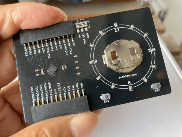
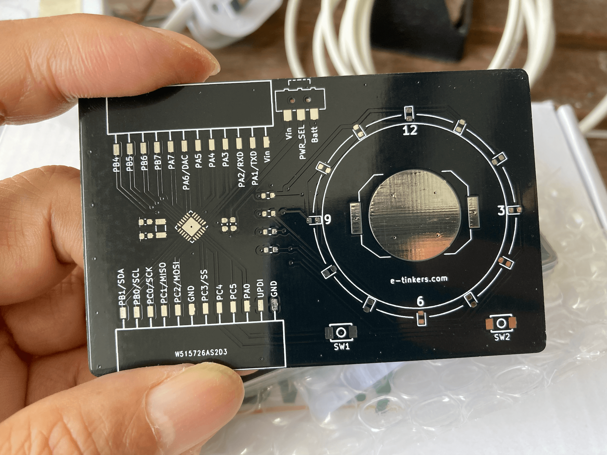
The PCB has arrived from PCBWay. It looks great with the black background.
PCB Front

PCB Component Side
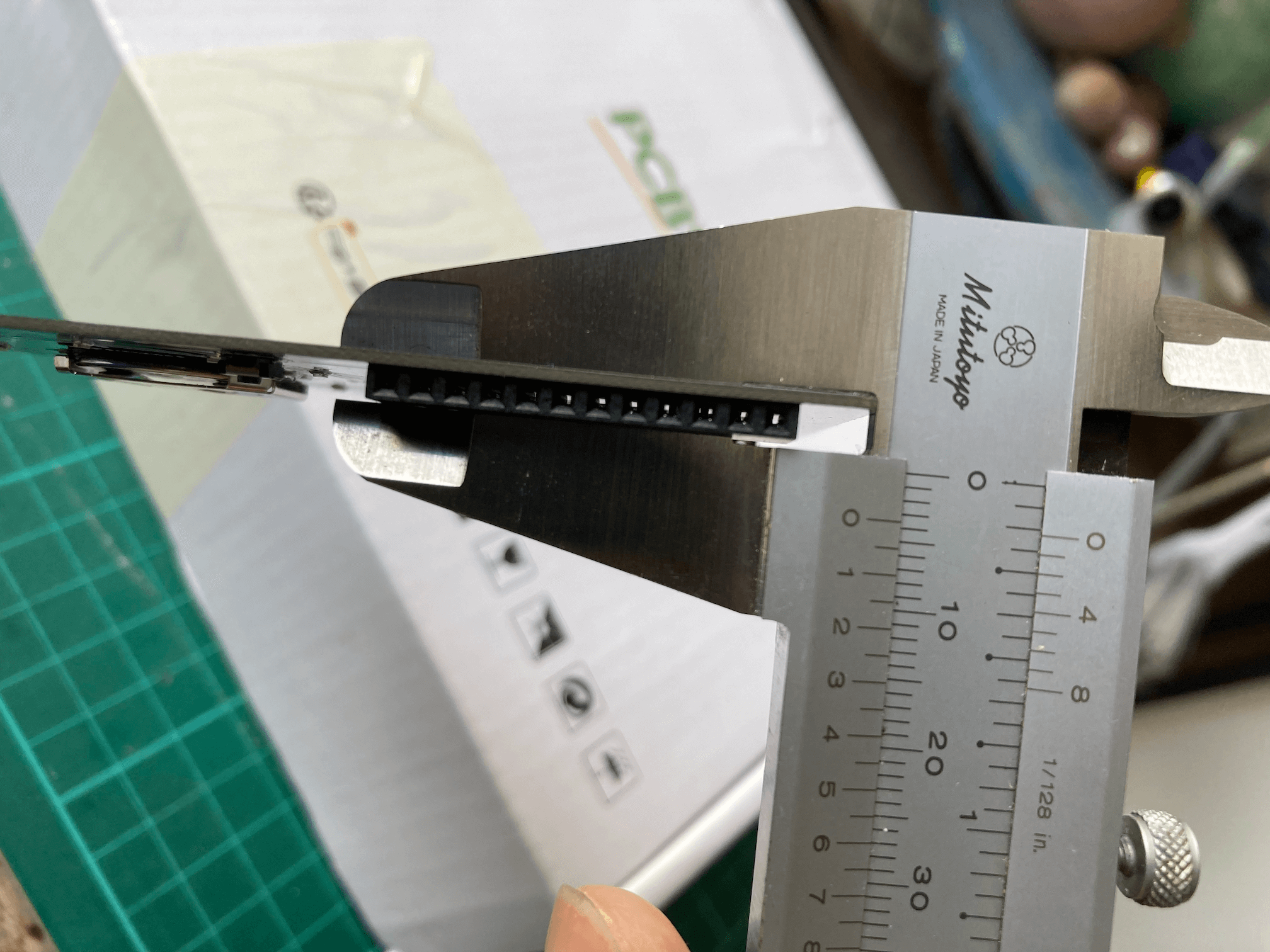
Since the VQFN package of ATtiny3227 is only 4 x 4 mm, so I ordered the stencil. The final assembly looks great. PCB thickness measurement shows that it is 3.2mm at the battery holder and 3.4mm at the break-out connector side.
PCB After Assembly

PCB Thickness Measurement
| Show time at 4:39 | Show time at 4:45 |
|---|---|
 |
 |
The project is very much completed by now. I will add one or two logs later on how I setup the toolchain and provide a couple of demonstration on how to use the business card as a ATtiny3227 development board.
ATtiny3227 Development Board
ATtiny 2-series
ATtiny3227 as part of the ATtiny 2-series (sometime is also referred as tinyAVR 2-series) is released in the middle of global Covid-19 pandemic, the ATtiny 0 and 1-series were released a couple of years earlier. Don't be fool by the name of ATtiny, it is not the classic ATtiny products such as ATtiny 31 or ATtiny 85, it is actually more powerful than many classic ATmega products such as the ATmega328P used in the Arduino Uno/Nano. Ever since its launch, I likely it very much and had ever since phase-out all my Arduino Uno/Nano/Pro Micro since 2017 with ATtiny 1 and 2-series for all my 8-bit MCU projects.
When using the board as an ATtiny3227 Development Board, it comes with the following peripherals and features
- 32kB Program Memory (Flash)
- 3kB RAM
- 256 bytes data EEPROM
- Capable of operating at 1.8 - 5.5v
- Running at up to 20 MHz with internal clock
- 6 channels Event System
- Configurable Custom Logic (CCL)
- Single pin UPDI programming interface
- 12-bit Differential ADC with Programmable Gain Amplifier / 15-channel ADC (Single-ended)
- 1 x Analog Comparator with internal DAC reference
- 1 x 16-bit Timer/Counter type A (TCA)
- 2 x 16-bit Timer/Counter type B (TCB)
- 1 x 16-bit Real Time Counter (RTC) with Periodic Interrupt Controller (PIT)
- 2 x USART
- 1 x SPI
- 1 x I2C
Software development can be done with Microchip's MPLAB X IDE or Microchip Studio IDE (Windows-only). It can be used as an Arduino by installing megaTinyCore to the Arduino IDE. Personally, I setup my own development environment with avrdude, VS Code and avr-gcc that I described previously.
The ATtiny3227 requires a UPDI programmer for uploading code to the device. A SerialUPDI programmer can be created using a USB-Serial Adaptor.
Specifically to this Business Card board, when using it as an ATtiny3227 board, the Slider Switch SW3 allows to select the power source either from the 3V 2016 coin cell battery or from external power source via the Vin pin on the break-out connector. This allows user to connect a 1.8v, 3.3v or 5v power source and program the chip to run up to 20MHz through the setup of the fuse and the configuration of the prescaler in the CLKCTRL register.
Bare metal programming
So far what I shown in my software implementation are based on bare metal (i.e. directly access the registers in ATtiny3227) programming, the new ATtinys are easy to program, and I high recommend to read the Tech Brief "AVR1000b: Getting Started Writing C code for AVR" first. The section 3.1 of the ATtiny3227 datasheet is a table called "I/O Multiplexing" which is kind of the pinmap of the MCU and probably the most-often-refer-to page for bare metal programming.
Here is a blinky program when using the board as a ATtiny3227 development board, there is not much different from any blinky program, except that the SW3 should be switch to Vin and connect a 5v power source through the Vin pin on the break-out connector so that the board can be programmed to run at 20MHz. Remember to change the F_CPU value in Makefile as well as in .vscode/c_cpp_properties.json to F_CPU=20000000UL prior compiling the code if you choose to follow my development environment setup.
As our board has 12 LEDs, any one of the LEDs can be used as the blinky LED, except that all the LEDs is part of the charlieplexing configuration, so it need to keep the unrelated charlieplexing pins "float" and only configure the two pins corresponding to the LED that you'd like to blink. The code shows the use of LED D12 as the blinky LED.
#include <avr/io.h>
#include <avr/interrupt.h>
#include <util/delay.h>
#include <stdio.h>
#include <stdlib.h>

#define BAUD_RATE 115200UL

static int USART0_sendChar(char c, FILE *steam) {
    while (!(USART0.STATUS & USART_DREIF_bm)); // Wait if Data Register Empty Interrupt Flag is not set
    USART0.TXDATAL = c;
    return 0;

}

static FILE USART_stream = FDEV_SETUP_STREAM(USART0_sendChar, NULL, _FDEV_SETUP_WRITE);

static void USART0_init(uint32_t baud_rate) {

    PORTA.DIRSET = PIN1_bm;                        // PA1 as TxD
    PORTMUX.USARTROUTEA |= PORTMUX_USART0_ALT1_gc; // map PA1 as alternative pin for TXD

    USART0.CTRLC = USART_CMODE_ASYNCHRONOUS_gc | USART_PMODE_DISABLED_gc | USART_SBMODE_1BIT_gc | USART_CHSIZE_8BIT_gc;
    USART0.BAUD = (uint16_t) (F_CPU * 64 / (16 * (float) baud_rate) + 0.5);
    USART0.CTRLB |= USART_TXEN_bm;

    stdout = &USART_stream;

}

void configLED12() {

  PORTB.DIRCLR = PIN5_bm | PIN6_bm;  // reset PB5 and PB6 to INPUT
  PORTB.DIRSET = PIN4_bm | PIN7_bm;  // set PB4 and PB7 as OUTPUT for controling LED D12
  PORTB.OUTCLR = PIN4_bm | PIN7_bm;  // reset both pins's state to LOW

}

int main(void) {

    char str[] = "Hello World";

    // clear Prescaler to run at 20MHz
    _PROTECTED_WRITE(CLKCTRL.MCLKCTRLB, !CLKCTRL_PEN_bm);

    USART0_init(BAUD_RATE);

    configLED12();

    while (1)
    {
        printf("%s\n", str);
        PORTB.OUTTGL = PIN7_bm;  // toggle LED D12 (PB7 HIGH/LOW, while PB4 remains LOW)
        _delay_ms(1000);
    }

    return 0;
}
The silkscreen on our board shows that the USART port is at PA1 (TXD) and PA2(RXD), a closer look at the I/O Multiplexing table indicated that the pins are the alternative pins for USART0 and the default pins for USART1. You can either use the USART0 (with alternative pins) or USART1. The code we used configures the USART0 and set the altenative pin position through PORTMUX configuration. For routing USART output to stdout, you can further read at Microchip Tech Brief TB3216 Getting Started with USART for more details.
Using it as an Arduino with megaTinyCore
From time to time I still use Arduino IDE, mainly because I don't want to re-invent the wheel of writting some of the sensor/device driver libraries. The installation of megaTinyCore is available on the megaTinyCore github page.
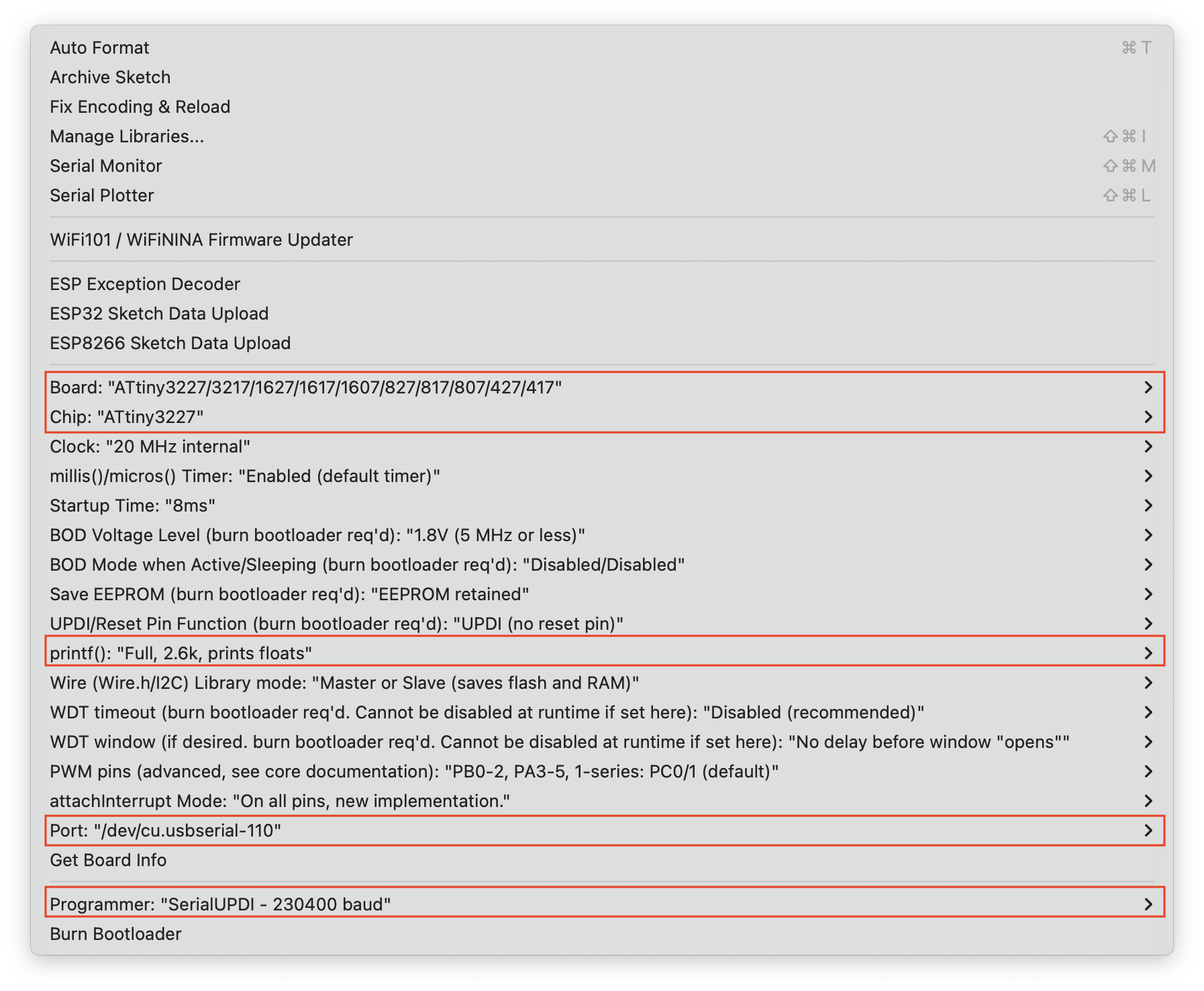
The sketch read the data from an SHT41 temperature/humidity sensor and display the data on a SSD1306-based OLED display at every 30 seconds. The code is very straightforward just like any Arduino code. Since I'm using the sprintf() function for formatting the floating point value, so other than configuring the usual setting on the Tools -> Boards from the Arduino IDE drop down, the printf() option need to be turned on as shown below.
#include <Wire.h>
#include <SHTSensor.h> // provided by Sensirion. https://github.com/Sensirion/arduino-sht
#include <SSD1306Ascii.h>
#include <SSD1306AsciiWire.h>

#define OLED_ADDRESS 0x3c

SHTSensor sht(SHTSensor::SHT4X);
SSD1306AsciiWire oled;

/* A helper function to print the degree symbol on LCD display */
void printDegreeSymbol() {
  const char degree[6] = {0x00, 0x06, 0x09, 0x09, 0x06, 0x00};
  Wire.beginTransmission(OLED_ADDRESS);
  Wire.write(0x40);
  for (uint8_t i=0; i<6; i++) {
    Wire.write(degree[i]);
  }
  Wire.endTransmission();
}

void setup() {
  Wire.begin();
  Wire.setClock(400000L);
  delay(10);
  oled.begin(&Adafruit128x32, OLED_ADDRESS);
  oled.clear();
  oled.setFont(lcd5x7);
  oled.set2X();

  if (!sht.init()) {
    oled.print("SHT Failed");
    while(1);
  }

  oled.setCursor(0, 0); oled.print("Tmp:");
  oled.setCursor(0, 2); oled.print("R/H:");
  oled.set1X();
  oled.setCursor(108, 0); printDegreeSymbol();
  oled.setCursor(108, 2); oled.print("%");
  oled.set2X();

}

void loop() {

  double t{0.0};
  double h{0.0};

  if (sht.readSample()) {
    t = sht.getTemperature();
    h = sht.getHumidity();
  }

  char msg[20] = {0};
  sprintf(msg, "%2.1f", t); oled.setCursor(60, 0); oled.print(msg);
  sprintf(msg, "%2.1f", h); oled.setCursor(60, 2); oled.print(msg);

  delay(30000);

}
One more thing ...
When I was doing the PCB design for the business card, I decided to create a derivative design based on the Business Card, so I created a wristwatch based on the Business Card design.

The writstwatch shares the same firmware used in the business card project, it has the same BOM with the exception of the two buttons used and without the two 12-pin break-out connector. I found a 16mm-wide wrist belt from Aliexpress and bought a few of them with different colors.
Since the wristwatch is not part of this contest, so I won't talk much about it here, and you can find the Kicad PCB design files from my Github repository.
Have a nice Hackaday!