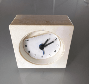
I had a classic Ikea clock that damaged by the leaking battery, during the new year cleaning, my family decided to throw it away, I took it back from trash bin and thinking of a weekend tinkering project to turn it into a digital clock.
The Idea
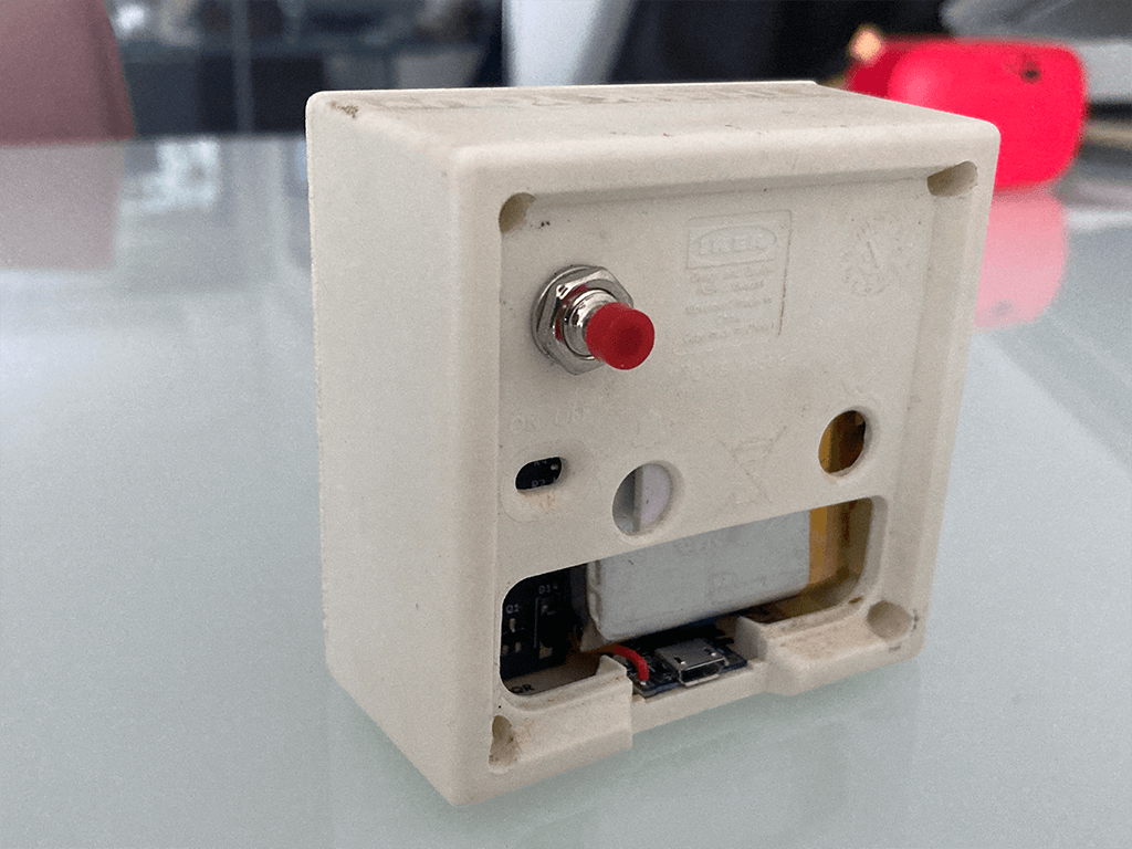
The clock is not in a good shape when I retrieved it from trash bin, the clock faceplate has peel off that curved up like old paint on a wall, the battery contacts are corroded by leaking Alkaline battery, and battery cover on the back has long gone.
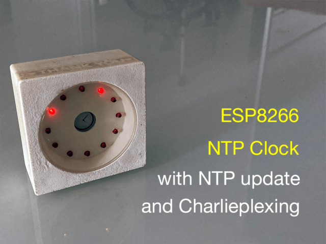
Inspired by Technoblogy's Tiny Time 2 Watch project, I wan't to create my own version of it. The clock face will consists of 12 LEDs, and light-up once every minute to tell the time. The Tiny Time Watch uses a DS2417 RTC chip and an ATtiny85. I don't have any DS2417 nor the ATtiny85, but I have several ESP8266 modules with me, so I could have the ESP8266 connect to WiFi and get the time from NTP server as the clock source instead of using a hardware RTC chip. This will also solve the need for manually adjusting the time. Another design consideration is to have it run on a Li-Po battery that could last for several months without charging.
The Clock Face
The clock face consists of 12 LEDS, just like tradition mechanical clock, at any giving time, two LEDs would light-up, one represents the hour, and another represents the five-minute interval.
In order to differentiate the two light-up LEDs, I decided that the one represents the hour will stay On for the display period, and the one that represents the five-minute interval will flash based on the minute passed by. For example, for displaying time of 5:13, both LEDs at postion 2 and position 5 (12'o clock is consider position 0) will light-up, but the one at position 2 will flash with 3 flashes to represent 10 pass 3 minutes, that is 13 minutes. If the time is exactly at a five-minute interval, like 5:10, instead of zero flash, I made it to have a long flash to distinguish from 1 (which is a short blinking).
0 - Long flash (450ms on, 50ms off) once
1 - short flash (50ms on, 50ms off) once
2 - short flash (50ms on, 50ms off) twice
3 - short flash (50ms on, 50ms off) three times
4 - short flash (50ms on, 50ms off) four times
Charlieplexing
In order to drive 12 LEDs, a multiplexing scheme need to used to minimize the number of GPIO pins required to drive the LED, as an ESP8266 module like ESP-12 doesn't have a lot of GPIO pins available. Charlieplexing is a multiplexing technique that allows you to uses n GPIO pins to drive n2 - n LEDs, that is, only 4 GPIO pin are required to drive 42 - 4 = 12 LEDs.
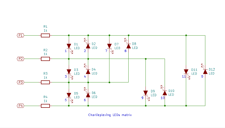
The diagram shows how I wired my 12 LEDs, the LED assignment correspond to the postion of the LED on the clock face, LED12 is designated as 0. The concept of Charlieplexing is quite simple, at any giving time, only one LED is light-up based on the states of the input pins, for example, in order to turn on LED1, a positive voltage is apply to P1 and a zero (ground) need to be asserted at P2, P3 and P4 would have to be "disconnected" by putting it in tri-state/high impedence mode. For microcontroller, we could turn those pins to "input" mode which effectively put those pins in high impedence mode.
Which LED to turn on is a combination of which combination of GPIO pins needs to be configured in OUTPUT mode, or INPUT mode, and which pin needs to be in HIGH or LOW state. I created a 3-dimension array to represent the 12 LEDs.
// GPIO pins
#define P1         5   // D1
#define P2         12  // D6
#define P3         13  // D7
#define P4         14  // D5

// Charlieplexing configuration and state matrix
#define PIN_CONFIG 0
#define PIN_STATE  1
#define LEDS       12
const uint8_t mux[LEDS][2][4] = {
//{ {         PIN_CONFIG             }, {        PIN_STATE       } }
//{ {  P1,     P2,     P3,     P4    }, {  P1,   P2,   P3,   P4  } }
  { { OUTPUT, INPUT,  INPUT,  OUTPUT }, { LOW,  LOW,  LOW,  HIGH } },  // 0
  { { OUTPUT, OUTPUT, INPUT,  INPUT  }, { HIGH, LOW,  LOW,  LOW  } },  // 1
  { { OUTPUT, OUTPUT, INPUT,  INPUT  }, { LOW,  HIGH, LOW,  LOW  } },  // 2
  { { INPUT,  OUTPUT, OUTPUT, INPUT  }, { LOW,  HIGH, LOW,  LOW  } },  // 3
  { { INPUT,  OUTPUT, OUTPUT, INPUT  }, { LOW,  LOW,  HIGH, LOW  } },  // 4
  { { INPUT,  INPUT,  OUTPUT, OUTPUT }, { LOW,  LOW,  HIGH, LOW  } },  // 5
  { { INPUT,  INPUT,  OUTPUT, OUTPUT }, { LOW,  LOW,  LOW,  HIGH } },  // 6
  { { OUTPUT, INPUT,  OUTPUT, INPUT  }, { HIGH, LOW,  LOW,  LOW  } },  // 7
  { { OUTPUT, INPUT,  OUTPUT, INPUT  }, { LOW,  LOW,  HIGH, LOW  } },  // 8
  { { INPUT,  OUTPUT, INPUT,  OUTPUT }, { LOW,  HIGH, LOW,  LOW  } },  // 9
  { { INPUT,  OUTPUT, INPUT,  OUTPUT }, { LOW,  LOW,  LOW,  HIGH } },  // 10
  { { OUTPUT, INPUT,  INPUT,  OUTPUT }, { HIGH, LOW,  LOW,  LOW  } }   // 11
};

void turnOnLED(uint8_t led) {

  pinMode(P1, mux[led][PIN_CONFIG][0]);
  pinMode(P2, mux[led][PIN_CONFIG][1]);
  pinMode(P3, mux[led][PIN_CONFIG][2]);
  pinMode(P4, mux[led][PIN_CONFIG][3]);

  digitalWrite(P1, mux[led][PIN_STATE][0]);
  digitalWrite(P2, mux[led][PIN_STATE][1]);
  digitalWrite(P3, mux[led][PIN_STATE][2]);
  digitalWrite(P4, mux[led][PIN_STATE][3]);

}

void turnOffLED() {

    pinMode(P1, INPUT);
    pinMode(P2, INPUT);
    pinMode(P3, INPUT);
    pinMode(P4, INPUT);

}
To turn on an LED, a function is called by passing in the LED number, and the turnOnLED() function will config the correct pinMode() and output state with digitalWrite(). To turn off any LED, simple call turnOffLED() function which configures all the pins to INPUT mode.
void testLED() {

    for(int l = 0; l < LEDS; l++) {
        turnOnLED( l );
        delay( 5000 / LEDS );
    }

}

void setup() {

}

void loop() {
    testLED();
}
I test the circuit with an ESP8266 D1 Mini and wired the LEDs matrix in a breadboard, as it is quite easy to get confuse on which wire should connect to which LED and pin, I wrote a simple sketch that blinking the LEDs from 0 to 11. It help to correct a few mistakes made in wiring.
ESP8266 WiFi - How to speed up connection
Anyone who uses ESP8266 before know how to connect to WiFi but I bet many do not know what exactly going on behind each WiFi function call. As I want to power the clock with a Li-Po battery for as long as possible, and ESP8266 consumed quite a lot of power when WiFi modem is turn on, so I spent quite some time trying to understand how exactly each WiFi function works.
It generally take about 6 seconds between establishing a WiFi connection with Arduino API WiFi.begin(ssid, password) till the WiFi.status() returns a WL_CONNECT state. Most of the time during the 6 seconds are spend on scanning the network to generate a list of Access Points and associated inforamtion about each Access Point, such as SSID, channel, and MAC Addesss (a.k.a BSSID - Basic Service Set Identification) within the reachable area. For 2.4GHz WiFi technology, there are total of 12 channels within the WiFi spectrum, so it take time to scan each of the channel, looking for various Access Points that operates within each channel. However if you know the BSSID and the channel of your Access Point is operating at, then you could speed up the scanning and shorten the time for establishing a connection. This will works until one day you change your router, you will then need to find out the Mac Address of the new router again. To find out the Mac Address, it requires to run a sketch to find out the channel and bssid first with a simple sketch.
#include <ESP8266WiFi.h>

const char* ssid = "your wifi ssid";
const char* password = "your wifi password";

void setup() {
    Serial.begin(74880);

    WiFi.begin(ssid, password);
    while (WiFi.status() != WL_CONNECTED) {
      delay(100);
    }
    Serial.printf("\nWiFi channel: %d\n", WiFi.channel());
    Serial.printf("WiFi BSSID: %s\n", WiFi.BSSIDstr().c_str());
}
This will print out the channel number and the BSSID of the Access Point.
WiFi channel: 2
WiFi BSSID: 7C:8B:CA:31:61:91
We can then use those information to establish a WiFi connection. The BSSID displayed above need to be re-arranged as an array instead of a string. With this change, I managed to cut the connecting time from 6+ seconds down to just slightly longer than 2 seconds on average.
#include <ESP8266WiFi.h>

const char* ssid = "your wifi ssid";
const char* password = "your wifi password";
const int channel = 2;
const uint8_t bssid[] = {0x7C, 0x8B, 0xCA, 0x31, 0x61, 0x91};

void setup() {
    Serial.begin(74880);

    WiFi.begin(ssid, password, channel, bssid);
    while (WiFi.status() != WL_CONNECTED) {
      delay(100);
    }
}
This however still rely on DHCP server in the router to assign an IP, the round trip must take some time, I'm curious on how much time I can cut down by using a static IP, it turns out I further reduce the time for establshing a WiFi connection by another 500ms.
#include <ESP8266WiFi.h>

const char* ssid = "your wifi ssid";
const char* password = "your wifi password";
const int channel = 2;
const uint8_t bssid[] = {0x7C, 0x8B, 0xCA, 0x31, 0x61, 0x91};
IPAddress ip(192, 168, 0, 120);
IPAddress gateway(192, 168, 0, 1);
IPAddress subnet(255, 255, 255, 0);
IPAddress dns(1,1,1,1);

void setup() {
    Serial.begin(74880);

    WiFi.persistent(false);
    WiFi.mode(WIFI_STA);
    WiFi.config(ip, gateway, subnet, dns);
    WiFi.begin(ssid, password, channel, bssid);
    while (WiFi.status() != WL_CONNECTED) {
      delay(100);
    }
}
One more thing about WiFi.begin() is that each time a WiFi connection is established, it will save the SSID to flash memory, and each time when the WiFi.begin() is called, it actually first read the WiFi configuration from the flash memory, but instead of using it to establish the connection, it actually take the one pass-in through the function call parameter to establish the connection, as stupid as it sounds, this not only waste of time, it wearing off flash memory too. WiFi.persistent(false) tell the ESP8266 not to bother to save to the SSID to the flash memory.
Getting time from NTP server
The purpose of having WiFi connection is because I want to access to a NTP server to get network time. ESP8266 supports sntp via lwip package, so there is no need for extra library and dependency like most of the online tutorials are showing. configTime() from the good old c time.h library (ctime in C++) would establish a sntp connection with a NTP server, once it is established, it set the update by default to once every hour. UTC_TEST_TIME is just a random timestamp in the past to be used to compare with the current time that return by the time(nullptr) function. The yield() is necessary while waiting for the time to be synchronised to keep the ESP8266 watchdog timer happy (to feed the dog so to speak).
#include <time.h>

// RTC Time constants
#define TIME_ZONE           28800       // GMT + 8
#define DAY_LIGHT_SAVING    0
#define UTC_TEST_TIME       1649289600  // Thu, 07 Apr 2022 00:00:00 +0000

void setup() {

    // The WiFi connection code shown previously

    configTime(DAY_LIGHT_SAVING, TIME_ZONE, ntpServer);
    while (time(nullptr) < UTC_TEST_TIME) {
        yield();
    };

    WiFi.disconnect(true);
    WiFi.mode(WIFI_OFF);
    WiFi.forceSleepBegin();
    delay(1);

    displayStart = millis();

}
When WiFi is on, it will draw 70mA current on average. Once the NTP time is sync, WiFi is no longer need, so WiFi can be turn off to bring the power consumption down to about 15mA with modem sleep mode.
Display Time
With the NTP access setup, we can obtained the time and use it derive the hour, the five-minute interval, and the number of flashes that we need to display the time. The time(nullptr) return a timestamp of current UTC time, which is used to pass into the localtime() function to get localtime, the localtime return the pointer to a struct tm that consts all the information about current local time, we only interested on hour and minute. The tm_hour from the struct is in 24-hour notation, we converts it to 12 hour with tm_hour % 12, the five-minute interval is simply tm_min divided by 5 which give us a value of 0 - 11, the number of flashes is the tm_min % 5. So a time of 17:13 would be represented as:
hour = 17 % 12 = 5
five-minute interval = 13 / 5 = 2
number of flashes = 13 % 5 = 3
void loop() {

    // testLED();

    time_t now = time(nullptr);
    struct tm* t = localtime(&now);

    uint8_t hour = t->tm_hour % 12;
    uint8_t fiveMinuteInterval = t->tm_min / 5;
    uint8_t flashes = t->tm_min % 5;

    turnOnLED(hour);
    delay(1);
    flashLED(fiveMinuteInterval, flashes);
    delay(1);

}
State Machine LED Flashing
To display the hour, we simply call turnOnLED(hour). To display the five-minute interval, however, a state machine is required as it is not only need to turn the LED on and off in a non-blocking manner for the need of multiplexing the LEDs, there is also several iteration within a given display time. I decided to set the total display time to 5 seconds, each flash last for 500 ms, a long flash that represents 0 minute will be turning LED on for 450ms, and off for 50ms, and for short flash that represents 1 minute after the five-minute interval would be 50ms on and 450 ms off. The code simply moving from one state to next state based on the time passed-by, there are a few timers to track the time need for LED to stay on or stay off.
// state machine variables
enum States {BEGIN, LED_ON, LED_OFF, END};
uint8_t flashState = BEGIN;
uint8_t cycle = 0;
unsigned long onTimer = 0;
unsigned long offTimer = 0;
unsigned long intervalTimer = 0;
unsigned long displayStart = 0;

void flashLED(uint8_t theLED, int flashes) {

    switch(flashState) {
      case BEGIN:
          onTimer = millis();
          flashState = LED_ON;
          break;
      case LED_ON:
          {
              turnOnLED(theLED);
              if (flashes == 0) {
                if (millis() - onTimer > 450) {
                    flashState = LED_OFF;
                }
              }
              else {
                if (millis() - onTimer > 50) {
                    flashState = LED_OFF;
                    offTimer = millis();
                }
              }
          }
          break;
      case LED_OFF:
          {
              turnOffLED();
              if (flashes == 0) {
                if (millis() - offTimer > 50) {
                    intervalTimer = millis();
                    flashState = END;
                }
              }
              else {
                if (millis() - offTimer > (500UL - 50 * flashes)/flashes) {
                  if (++cycle < flashes) {
                      flashState = BEGIN;
                  }
                  else {
                      flashState = END;
                      intervalTimer = millis();
                  }
                }
              }
          }
          break;
      case END:
          if (millis() - intervalTimer > 1000UL) {
              flashState = BEGIN;
              cycle = 0;
          }
          break;
      default:
          break;
    }

}
ESP8266 Deep Sleep and Battery Life Estimation
As mentioned before, by using various technique, the WiFi is only on for less than 2 seconds, then it is turned off to save the power. Displaying time take 5 seconds without WiFi. According to Epressif's test. The average power consumption when WiFi is connected, it consumed an average of 80mA, and about 15mA when WiFi is swtiched off. The deep sleep however consumed only 10uA.
As the clock casing only be able to fit in a 1000mAH battery that I have, I intend to only wake-up the ESP8266 every 5 minutes during day time (i.e. 12 wake-up/hour), the "night mode" will start from 22:00 till next day 7:00 and during this period, it will only wake up once per hour. This will help to greatly extend the battery life. With the help of an excel spreadsheet, I estimated that for a 1000mAH Li-Po battery, this will last for about 50 days before it needs for charging.
#define DISPLAY_TIME        5000
#define NIGHT_MODE_START    22          // night mode started after 22:00 (10:00pm)
#define NIGHT_MODE_END      7           // night mode ended after 7:00 (7:00am)
#define DAY_SLEEP_TIME      300e6        // 300 seconds (5 mins)
#define NIGHT_SLEEP_TIME    3600e6      // 1 hour

void loop() {

    // time and LED control code shown previouly

    while (millis() - displayStart > DISPLAY_TIME) {
        if (t->tm_hour > NIGHT_MODE_START && t->tm_hour < NIGHT_MODE_END)
            ESP.deepSleep(NIGHT_SLEEP_TIME);
        else
            ESP.deepSleep(DAY_SLEEP_TIME);
    }
}
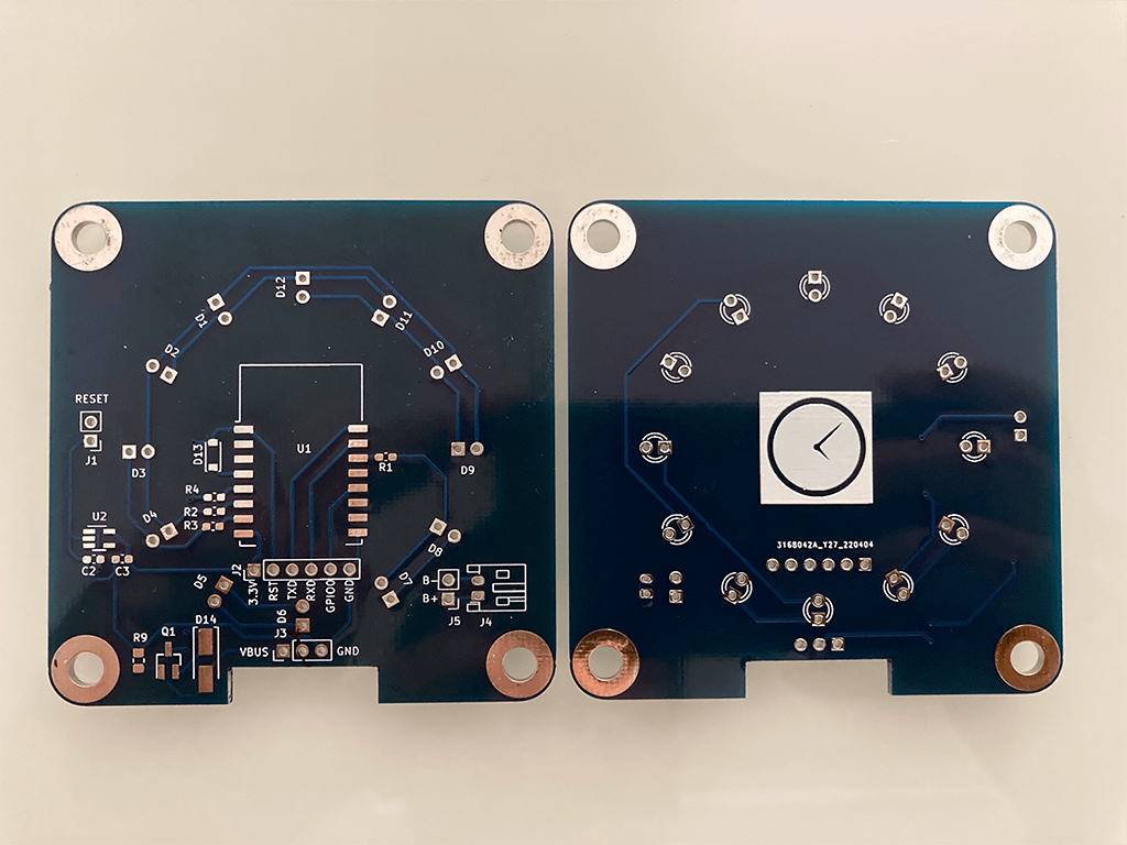
The Hardware Design
I did all the test on a breadboard with an ESP8266 D1 Mini. As the wiring of charlieplexing can be quite messy and the I have several ESP-12S modules with me, so I decided to create a PCB.
When I clean up the front facing, it leaves a big hole in the middle of clock face, so I decided to create a clock silkscreen to cover it, and it turns out to be quite nice.
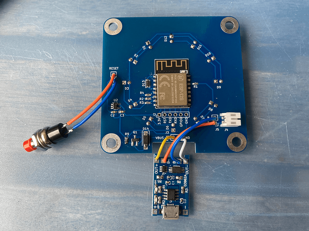
I decided not to include a charger in the PCB design, as I still have a few TP4056 charging module from Aliexpress with me. It usually cost less than 2 US Dollars for 5 pieces, and there are two version of the TP4056 charging modules, one without the charging projection circuit designed for using with the Li-Po batteries that already have the charging protection circuit build into the battery, another version which comes come with the protection circuit, usually for those batteries such as 18650 which does not contains any built-in projection. For my case, the version without protection circuit should be used, but I only have the one with built-in protection, so I use it for time being and remind myself to replace this in furtue.
Having the TP4056 module is not enought because the TP4056 lack of load sharing functionality that allows charging the battery while power the device, plus the ESP8266 can only operate between 3.0V-3.6V, a 3.7V (at fully charge could be at 4.2V) Li-Po need to have a voltage regulator to bring the supply voltage down to 3.3V, so I add a circuit for load sharing with a 3.3V LDO.
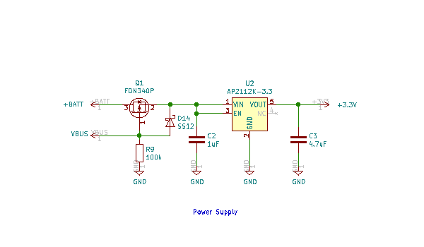
When the device is charging via USB port, the voltage on VBUS supply the power to the device via D14, it also turn off the P-channel MOSFET which disconnect the battery from the circuit. When VBUS is not present, the MOSFET is switched on, and the power is supply by the battery.
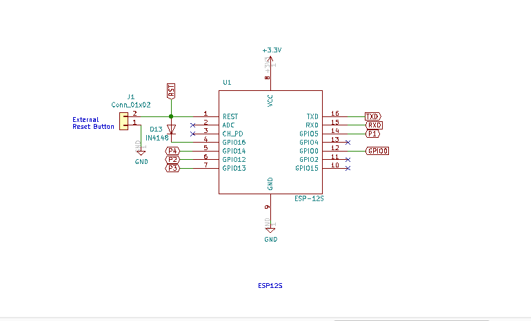
The nice thing about ESP-12S module as compare to ESP-12E/F or older ESP-12 is that all the pull-up/pull-down resistors, decoupling capacitors are built-in, making it quite neat with minimum external components required. The only two components that I add is a diode connecting between GPIO16 and RESET pin of the ESP12-S module for waking up the ESP12-S from deep sleep. The diode make it possible to programming the module without the need for disconnecting the GPIO16. Another component add is an external RESET switch (which is off the PCB) so that whenever I want to check the time, I could just press the RESET button to manually wake up the ESP-12S instead of waiting for 5-minute for the ESP-12S to display the time.
Other than the PCB fabrication, I didn't buy any compoents as all come from my inventory, so if you read my PCB files, you might noticed that resistor R9 has a footprint size of 0805 while the rest of the SMD components are in 0603 size, this project really utilizes whatever I have.
Summary
This is one of those my weekend projects, it turns into a multiple-weekend project from conceptualise it, to design and write the code for it, and eventually build it, but I learnt a few things from the project, Charlieplexing is an intersting "ancient" technique for multiplexing and fits perfectly in this applicaiton. I learnt a few tricks and gained deeper understanding on how the ESP8266 WiFi actually works through reading the source code and research online.
Resource
The PCB design files can be found from my github ESP8266_ntp_clock_PCB
The complete source code can be found form my github ESP8266_ntp_clock
Read NTP Clock Project Revisit to see how to improve the battery life to more than 150 days!
very good design and information. i owe you a good coffee. thanks
Thanks a lot! This seems way better than all the clocks I’ve seen based on NTPClient. One note is that the arguments to configTime seem out of order. This works fine on ESP8266, but did not pick up the time zone properly on ESP32 (where maybe the dst argument is treated as a flag instead of an hour offset?). I put them in the proper order and it works on both my boards.
ESP8266 internal iwIP’s implementation of
configTime(DAY_LIGHT_SAVING, TIME_ZONE, ntpServer)API is different from ESP32’sconfigTime(gmtOffset_sec, daylightOffset_sec, ntpServer), Noticed that the first two parameters are swapped.