For the past several months, I've been searching for a cost-effective pH and EC sensor kit and I evaluate Seeed Studio's new pH sensor kit and EC sensor kit this week.
This is going to be a two-part articles, I will mainly discuss my review and test on Seeed Studio's pH Sensor kit on this part, and I will take a look at the Seeed Studio's EC Sensor kit on part 2.
Singapore 30 by 30 vision and Urban Farming
With the announce of Singapore 30 by 30 vision by the Singapore government more than a year ago, Singapore has an ambitious target of producing 30 per cent of the country's food needs by 2030 within the tiny island, over the past year, several land auctions have been conducted to alocate various lots of farm lands to qualified bidders in phases. In order to achieve the vision all farmers have no choice but to utilise technology to boost its yield and land-use efficiency to meet the audit requirements starting from 3rd year of the operation. Singapore government recently further announce the plan to cover some of the
Singapore Multi-storey carpak rooftop for farming purpose.
Over the past half year or so, I've been busy in evaluation products and developing IoT platform and backend solution for hydroponics/urban farming application. Now I have a ready-to-deploy system, including the sensor node, wireless solution, battery management as well as backend server and dashboard for hydrponic applications. However this doesn't means the job is done, I previously discussed my experience of using a unknown pH sensor board that is common available in Chinese e-commerce platforms, the board works but 2/3 of the board circuitry are very much useless, and I've been in searching for a better, cost-effective solution since. This week I got the chance to test out Seeed Studio's pH and EC sensor kits.
Seeed Studio pH and EC sensor kits
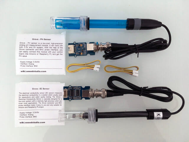
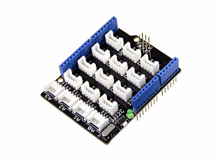
Each kit comes with an electrode, a sensor board and a Grove cable with female connectors at both end. All Seeed Studio boards have its signature Grove connector, it was designed to be used together with Grove Base Shield for Arduino that can be attached to an Arduino Uno (There are similar shields designed to work for Arduino Nano or Arduino Mega, and other popular MCUs in the market), this allows user to be able to quickly connect sensor boards with Arduino Uno without extra jumper wires, provided you are buying your sensor board from Seeed Studio which uses the same Grove connector system. I personally don't use Arduino Uno so I didn't order the Grove shield, but you might want to consider to get one if you are using Grove sensor boards.
Seeed Studio Grove pH Sensor Kit
In case you never heard of Seeed Studio, Seeed is an IoT hardware provider based in Shenzhen, China, very much like China's Adafruit or Sparkfun. Seeed offering a wide array of hardware platforms and sensor modules ready to be integrated with existing IoT platforms, what is less known by many people is that Seeed also provide one-stop PCB fabrication and PCB assembly service.
The new Grove PH Sensor Kit (E201-C-Blue) is sold at US$15.9 and it seems to be a cost reduced version of the older one which is still listed on Seeed Studio Shop at US$29.9, judging from the circuit diagram and the sample Arduino sketch from Seeed Studio wiki, it seems that the boards for both SKUs are the same, but the new sensor kit was replaced with a new Blue ph eletrode (E201-C) and it does not packaged with the pH solutions. Seeed Studio previously has the problem in fullfilling international order for the older SKU due to airline restriction on fluid solution shipment. The electrode however still come with a tiny bottle of (I guess about 10-20ml) potassium chloride solution for keeping the electrode tip emerging in the buffer solution when it is in the protection cap.
How does Seeed Studio Grove pH Sensor board work?
The pH electrode is a passive sensor and does not need any excitation voltage or current. The source impedance of a pH probe is very high because the thin glass bulb has a large resistance that is typically in the range of 10 MΩ to 1000 MΩ. The Seeed Studio's Grove pH sensor board utlizes an OPA333 Operational Amplifier from TI, which has very low noise, and almost zero drift over temperature.
When the electrode tip is submerging in the fluid solution, the pH eletrode produces a voltage output that is linearly across a certain range. An ideal pH sensor produces zero voltage at a pH value of 7, and a positive voltage (a few hundred millivolts) when pH value go down, and a negative voltage when pH value go up, causing by the hydrogen irons forming at the outside (and inside) of the membrane glass tip of the pH electrode when the membrane comes into contact with solution.
The Seeed Studio ph sensor board provides a 1.8v reference voltage through a XC6206 voltage regulator, this reference voltage is used to "float" the input by 1.8v above the input reading from the electrode so that the negative voltage when pH value is above 7 can be represented as a voltage below 1.8v, and the positive voltage when the pH value is below 7 can be represented as a voltage above 1.8v. This make it possible for reading the eletrode reading through Analog-to-Digital (ADC) converter of an Arduino because an ADC can't read negative voltage.
pH Sensor Probe Calibration
As mentioned before, the relationship between voltage generated by the sensor probe and the pH value is a linear across a range. So what this means that it can be represented by a linear equation with a simple formula, this form the basis of pH sensor probe calibration as well as basic measurement of pH value.
y = k * x + b

or

phValue = slope * voltage + offset
Where slope means the slope of the linear line against a horizontal line, and the offset will be the phValue when the voltage is euqal to zero.
With this understanding, we can then obtain the slope (and offset) by using two known pH values and read the voltages at those pH values by using the following Arduino sketch (uncomment out the first line for running in Calibration Mode):
//#define CALIBRATION_MODE    //Uncomment out this line for Calibration Mode

#if ARDUINO_ARCH_STM32    // for STM32 with 12-bit ADC
  #define ADC_REF 3.3
  #define ADC_STEPS 4096
  / For SeeedStudio Probe with STM32
  #define offset 38.263
  #define slope -26.389
#else  // For AVR Adrduinos with 10-bit ADC
  #define ADC_REF 5.0
  #define ADC_STEPS 1024
  // For SeeedStudio Probe with Arduino - PH1=4.0, V1=1.397. PH2=6.86, V2=1.284
  #define offset 39.3577
  #define slope -25.3097
#endif

#define PH_PROBE A0       // pH eletrode probe connect to pin A0
#define PRINT_INTERVAL 1000

unsigned long timer = 0;

double getAverageReading() {
  int buf[40] = {0};
  // get 40 sensor readings
  for (int i=0; i < 40; i++) {
    buf[i] = analogRead(PH_PROBE);
    delay(5);
  }

  // Sort the readings in ascending order
  int temp;
  for (int i=0; i<40; i++) {
    for (int j=i+1; j<40; j++) {
      if (buf[i] > buf[j]) {
        temp = buf[i];
        buf[i] = buf[j];
        buf[j] = temp;
      }
    }
  }

  // discard first and last 10 values and average the rest of 20 values
  int sum = 0.0;
  for (int i=10; i<30; i++) {
    sum +=buf[i];
  }
  return (double)sum/20;
}

void setup() {
  Serial.begin(115200);
  delay(500);
#if ARDUINO_ARCH_STM32
  analogReadResolution(12);
#endif
}

void loop() {

  double adcValue = getAverageReading();
  double voltage = adcValue * ADC_REF / ADC_STEPS;

  if (millis() - timer > PRINT_INTERVAL) {
#ifndef CALIBRATION_MODE
    Serial.print("PH = ");
    double pHValue = slope * voltage + offset;
    Serial.println(pHValue, 2);
#else
    Serial.print("voltage = ");
    Serial.println(voltage, 3);
#endif
    timer = millis();
  }
}
Seeed Studio does not provide the buffer solution required for calibration, but powder form of pH buffer is cheap and can be purchased esily online. I use ph value of 4.0 and 6.86 for my calibration.
- Follow the instruction provided on the buffer powder to prepare the buffer solutions.
- To increase accurate, leave the probe in the prepared buffer solution for at least a couple of minutes before taking the reading as the result.
- To avoid cross contamination, dip the probe in distill water for a couple of minites before dipping it into a different buffer solution.
Put the pH electrode into the solution of pH4.0 for at least 1 minute and run the sketch, and noted down the voltage reading. Repeat the same process by putting the pH electrode into the solution of pH6.86 to get the new voltage reading. In my test case, the voltage is 1.284 at pH 6.86(let's called it v1), and voltage v2 is 1.397 at pH 4.00. With those two pH values and voltages, the slope of the line is:
k = (ph1 - ph2) / (v1 - v2)
  = (6.86 - 4.00) / (1.284 - 1.397)
  = - 25.3097
The offset of the line can be obtained:
offset = ( (ph1 - ph2) - slope * (v1 + v2) ) / 2
       = ( (6.86 - 4.00) + 25.3097 * (1.284 + 1.397)) / 2
       = 39.3577
The picture below provide a better visual illustration of the linear equation and the relationship between the slope and the offset and our measured values.
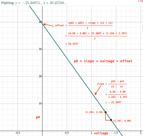
If you download the sample package from pH Sensor Kit wiki page, it came with an excel spreadsheet that allows you to plug in the ph and voltage values to get the slope and offset values.
Use of pH Sensor board
Once the calibration is done, all you need to do is to comment out the first line of the sketch (by adding // at the beginning of the first line), and update the values of #define slope and #define offset based on your calculation and the type of MCU (STM32 or Arduino) you are using, and re-compile the code, the code will now shown the actual pH value instead of the voltage reading.
//#define CALIBRATION_MODE    //Uncomment out this line for Calibration Mode

#if ARDUINO_ARCH_STM32    // for STM32 with 12-bit ADC
  #define ADC_REF 3.3
  #define ADC_STEPS 4096
  // For SeeedStudio Probe with STM32 only
  #define offset 38.263
  #define slope -26.389
#else    // For AVR Adruinos with 10-bit ADC
  #define ADC_REF 5.0
  #define ADC_STEPS 1024
  // For SeeedStudio Probe with Arduino - PH1=4.0, V1=1.397. PH2=6.86, V2=1.284
  #define offset 39.3577
  #define slope -25.3097
#endif
Please noted that the pH electrode that comes with the sensor kit is labotorary grade, it is not design for submerging into measuring solution permanently. If you want to use the sensor kit for actual deployment, or for hydroponics applicaiton, get an industrial-grade pH electrode (which usually can be emerged into measuring solution permanently with a lifecycling of around 3 years) and calibrate it at least once in every 6 months.
Power the board with 3.3v
Although the OPA333 Operational Amplifier is capable of operating at a wide range of supply voltage and Seeed Studio claims it works for both 3.3v/5v. Seeed Studio's design has an on-board 3.3v voltage regulator that take a maxium input voltage of up to 6v and convert it down to 3.3v to power the OPA333 op amp. this allows the board to be directly powered by any 5V MCU development boards such as Arduino Uno, as well to be powered by 3.7v li-po/li-ion battery. When powering with a 3.3v power source, I was a little bit concerned that the supply to the board after the voltage regulator would be below 3.3v due to the voltage drop on the regulator. The actual measurement shown that with 3.3v supply voltage, the supply voltage to the board after the voltage regulator is able to maintain at about 3.29v, thanks to the Low-Dropout voltage regulator XC6206. I'm quite happy that this board is capable of operate at both 5v and 3.3v as this making connecting with 3.3v MCUs such as STM32 blue pill a lot of easier and simplier.
Very Low Power Consumption
Although Seeed Studio didn't market the power consumption of this board as a key feature, however, I personally think the extremely low power consumption is an outstanding key feature of this board. The unknown pH sensor board that I tested previously constantly consumed average of 8mA, while this Seeed Studio pH sensor board has an average power consumption of less than 30uA! What this means is that if you power the board with a 2600mAh battery, it will last for 30 days without charging!
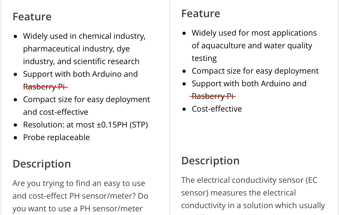
Does it works with Raspberry Pi?
On both of Seeed Studio' web pages for pH Sensor Kit and EC Sensor Kit, it shown under the "Feature" that it supports both Arduino and Raspberry Pi. The claims of supporting Raspberry Pi seems to be misleading as both sensors are analog sensors and Raspberry Pi does not have any any ADC input, it won't work for Raspberry Pi, at least not directly. I hope Seeed Studio will soon correct this false-claim.
Having said that, I noticed that Seeed Studio actually has a ADS1115 Shield for Raspberry Pi which provides an external 4-channel 16-bit ADC with an I2C interface, making it possible to get the ph sensor data on a Raspberry Pi. Personally I have not test it yet as I don't have the ADC shield, but it should not be difficult to connect the pH sensor board with the shield and write some Python script to get the data via I2C interface.
My little hack to get consistent readings
When I first start my testing of the pH sensor board, I used the sketch provided by Seeed Studio, and Seeed Studio's sketch read the sensor data at an interval of 20ms constantly, but only print the data to Serial Monitor every 1 second. Reading 40 data would take 800ms, Arduino ADC take 13 clocks to obtain an ADC reading, and by default Arduino has a clock speed of 16MHz and with a clock prescaler of 128, so what this means is that for each ADC reading, it takes Arduino about 104us (13/(16000000/128) to get a reading, so reading the pH value at 20ms interval is a lot waste of time in between.
I think this could be done a lot faster with shorter reading interval and I don't see why it need to constantly reading the data too, so I wrote my own sketch to read at much shorten interval (2ms) and only read the sensor when I need it (i.e. every 1 second when I want to output the data to Serial Monitor).
This is when I noticed that if I changed the sensing interval, the sensor board's readings changed. In another word, the board does not provide consistent readings at various sensing intervals. I swap my Arduino Nano with an STM32 Blue Pill (which has an ARM CORTEX-M3 MCU with 12-bit ADC) and experienced the same phenomenon. However, if I disconnected the Arduino and measure the output reading from the sensor board, the reading seems to be normal and stable. So the phenomenon seems to be related to the ADC of the Arduino (and STM32 too).
A quick search on ATMega328 datasheet, under the section 24.6.1 "Analog Input Circuitry", it said:
"The ADC is optimized for analog signals with an output impedance of approximately 10k ohm or less. If such a source is used, the sampling time will be negligible. If a source with higher impedance is used, the sampling time will depend on how long time the source needs to charge the S/H capacitor, with can vary widely. The user is recommended to only use low impedance sources with slowly varying signals, since this minimizes the required charge transfer to the S/H capacitor".
A closed look at the sensor board design, it seems already have impedance lower than what the Arduino ADC required. Further reading the OPA333 datasheet shows that the OPA333 has poor settling time of about 50 microseconds, the ADC sampling charge demand will initiate another settling behaviour. For a short term workaround, I added a 10k resistor between the input of the Arduino ADC and the ground. The resistor lowers the instantaneous peak output current, causing less of a transient inside the OPA333. I'm able to get consistent readings not only at any sensing interval (I tested at various intervals between 2ms up to original 20ms). I also tested it on both Arduino Nano and STM32 Blue Pill. This turn out works very well. However, this is not a good design by all means. The workaround also caused the output voltage from the sensor board to be reduced by 1/3 of the original voltage due to the voltage divider formed by the on-board R6 5.1k and the 10k resistors that I added.
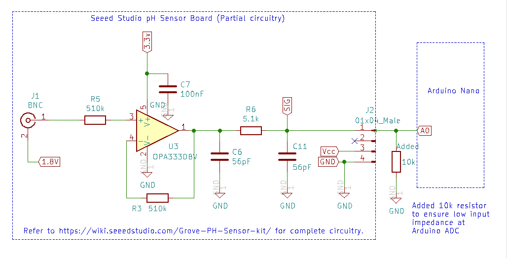
OPA333 is an operation amplifier with zero-drift, which means that it has relatively high peak input transient currents, and a pH sensor is extremely high impedance. So the problem that I'm facing could also due to the front-end design, that is, OPA333 might not be the right operational amplifier for pH sensor. I may need to do more experiencing to find out the true root cause.
Seeed Studio provided an example code at its ph Sensor Kit wiki page, however, I didn't use it but created my own for several reasons:
- I want the code to be able to use for both calibration and actual measurement with minimum changes;
- I want it to be able to run it on both Arduino and STM32, those boards have different ADC reference voltages (5v versus 3.3v) and resolution (10-bit versus 12-bit);
- The way Seeed Studio's code produces the average reading is taking 40 sample readings and drop the lowest and higher values, and sum-up the rest of 38 data to produce an average value, while I think it is better to provide a filtered value by dropping the first tand last 10 readings and sum-up the middle 20 values to produce a more stable average values;
- Seeed Studio average algorithm occasionally produces average values based on 5 data points instead of 40 data points, this caused the average reading flutuate slightly due to how the average is calculated;
- Seeed Studio code constantly reading sensor data at 20ms interval, this is not necessary. It only need to read the sensor data (40 data points) once when the data is needed.
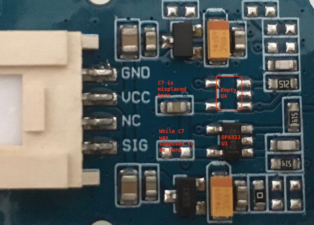
Misplacement of Capacitor C7 on PCB
During my close examination of the circuit diagram for doing my little hack, I noticed that a de-coupling capacitor C7 for OPA333 Op Amp was misplaced on where C8 capacitor is supposed to be (for an empty U4 op amp that was not placed on PCB), although this probably has minimum impact on actual performance, nevertheless, this is a careless mistake on PCB design.
Summary
Overall, I like Seeed Studio's pH sensor board a lot, it meet most of what I was searching for, many of those benefits come from the Operational Amplifier it used:
- Works with both 5v and 3.3v power source;
- Low power consumption;
- Stable voltage reference for measurement;
- Compact size;
- Cost-effective.
On the other hand, I'm also questioning whether OPA333 is a right chip for pH sensor application, the circuit design requires some minor hack in its current form in order to make a reliable reading across various MCU boards and at various sampling intervals. Further investigation and experiencing is required to make the board work consistently. I hope Seeed Studio could improve the design on its next iteration of design and production.
I look forward to testing out the EC sensor kit. Stay tune...
I’m currently doing research on all the things you are talking about to provide monitoring for my hydroponic system and send the data to my aws account. I plan to create a nice reporting tool with alarms for issues. I’m very interested in learning about the performance over time of the pH and probes. These pH probes seem to have a lifespan of six months or so and don’t appear to be designed for continuous use. I’d love to see your experience on this before I purchase. Lol. Thanks for posting.
Yes, those probes are hobby-grade or laboratory-grade, not design for emerging in solution for long time. You need to get Industrial-grade probe which alone could be as much as over $200.
Thanks Henry, The problem you encountered on ADC is exactly the same I am having, big variation of ADC data, and I was questioning too why taking every 20ms for 40 times of reading…I will follow your idea to optimize my codes, as well as adding components to have a robust hardware too…
The PH probe also concerns me in terms of life span. However, as home hydroponic system, we don’t really need such accuracy, it’s already better than those handheld PH pen…:-).