I recently did a range test over a pair of ESP-01 running ESP-Now, by no means its a comprehensive test, but it gives a better understanding of ESP-01 wireless performance and the ESP-Now protocol.
TL;DR
You can watch the YouTube video about the test.
ESP-Now Protocol
ESP-Now is a communication protocol developed by Espressif. It utilises 2.4GHz Wifi channels but instead of connecting to a WiFi router and DHCP server, it allows peer-to-peer communication between two ESP modules without going through the router. ESP-Now can send payload up to 250 bytes and depend on configuration, up to 20 peers. You can read more about the ESP-Now protocol from Espressif's ESP-Nowweb page.
Test Setup
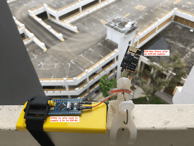
Two ESP-01 modules are used for the test, one is programmed as an ESP-Now Receiver and mounted at a fix location, as I don't have a stand-alone 3.3v regulator, I used a STM32 Blue Pill board as the power source for the 3.3v voltage, the STM32 itself is getting the power via USB port from a power bank.
Another ESP-01 module is programmed as an ESP-Now Controller(Transmitter) and connected via a USB to TTL adaptor board to my Mac. the USB-to-TTL adaptor board provides both the 3.3v power source and the serial communication interface so that the transmission stage can be viewed through the Serial Monitor of Arduino IDE.
ESP-Now Controller (Transmitter)
Although we are testing ESP-Now on ESP-01 modules, the codes here works for all ESP8266 modules. It is however does not works with ESP-32 without some modification because ESP-32 has slightly different APIs for ESP-Now implementation.
// esp8266-espnow-transmitter.ino
// This code works for ESP8266 only.
// ESP-NOW for ESP32 has different API from the ESP8266 implementation

#include <ESP8266WiFi.h>
#include <espnow.h>

#define RETRY_INTERVAL 5000
#define SEND_INTERVAL 1000

// Use the following pattern to create a Locally Administered MAC Address
//   x2-xx-xx-xx-xx-xx
//   x6-xx-xx-xx-xx-xx
//   xA-xx-xx-xx-xx-xx
//   xE-xx-xx-xx-xx-xx
// replace x with any hex value

// the following three settings must match the slave settings
uint8_t remoteMac[] = {0x82, 0x88, 0x88, 0x88, 0x88, 0x88};
const uint8_t channel = 14;
struct __attribute__((packed)) DataStruct {
  float temperature;
  float humidity;
};

DataStruct myData;

unsigned long sentStartTime;
unsigned long lastSentTime;

void sendData() {
  uint8_t bs[sizeof(myData)];
  memcpy(bs, &myData, sizeof(myData));

  sentStartTime = micros();
  esp_now_send(NULL, bs, sizeof(myData)); // NULL means send to all peers
}

void sendCallBackFunction(uint8_t* mac, uint8_t sendStatus) {
  unsigned long sentEndTime = micros();
  Serial.printf("Send To: %02x:%02x:%02x:%02x:%02x:%02x ", mac[0], mac[1], mac[2], mac[3], mac[4], mac[5]);
  Serial.printf("Temperature: %.2f ", myData.temperature);
  Serial.printf("Humidity: %.2f ", myData.humidity);
  Serial.printf("Trip micros: %4lu, ", sentEndTime - sentStartTime);
  Serial.printf("Status: %s\n", (sendStatus == 0 ? "Success" : "Failed"));
}

void setup() {
  WiFi.mode(WIFI_STA); // Station mode for esp-now controller
  WiFi.disconnect();

  Serial.begin(74880);
  Serial.println();
  Serial.println("ESP-Now Transmitter");
  Serial.printf("Transmitter mac: %s \n", WiFi.macAddress().c_str());
  Serial.printf("Receiver mac: %02x:%02x:%02x:%02x:%02x:%02x\n", remoteMac[0], remoteMac[1], remoteMac[2], remoteMac[3], remoteMac[4], remoteMac[5]);
  Serial.printf("WiFi Channel: %i\n", channel);

  if (esp_now_init() != 0) {
    Serial.println("ESP_Now init failed...");
    delay(RETRY_INTERVAL);
    ESP.restart();
  }

  esp_now_set_self_role(ESP_NOW_ROLE_CONTROLLER);
  esp_now_add_peer(remoteMac, ESP_NOW_ROLE_SLAVE, channel, NULL, 0);
  esp_now_register_send_cb(sendCallBackFunction);
}

void loop() {
  if (millis() - lastSentTime >= SEND_INTERVAL) {
    lastSentTime += SEND_INTERVAL;
    myData.temperature = 32.3;   // replace this with your actual sensor reading code
    myData.humidity = 70.8;      // replace this with your actual sensor reading code
    sendData();
  }
}
To simulated the actual sensor node operation, a hardcoded temperature and humidity reading data is used as the transmission payload and send at an interval of every 1 second.
For an ESP8266 (i.e. our ESP-01) to be an ESP-Now Controller (i.e. our Transmitter), the ESP8266 must be in WiFi Station mode, and disconnected from any AP that it previously connecting to. The Controller declares its role as an Controller, and then add each peer as a Slave with peer's MAC address, and the WiFi channel the Controller should listening to for the receiving data. The controller also register a callback event handler function so that when a message that is sent to the receiver is completed and the receiving peer acknowledged back, the callback function will be triggered to get the status of the transmission acknowledgement.
I chose channel 14 which is not used in Singapore (or most of Asia) for the test. You can find out about the list of WLAN channels from Wikipedia.
The WiFi channel, remote peer MAC address and the data structure of the payload must match the setting used in the peer(s).
A timer is setup to measure the time taken between sending the data to and the receiving of the acknowledgement from the peer, this not only give us some idea of how long does it take to complete a success transmission, it is also indicate the quality of the wireless link signal between the Controller and the Slave.
ESP-Now Slave (Receiver)
// esp8266-espnow-receiver.ino
// This code works for ESP8266 only.
// ESP-NOW for ESP32 has different API from the ESP8266 implementation

#include <ESP8266WiFi.h>
#include <espnow.h>

#define RETRY_INTERVAL 5000

// the following 3 settings must match transmitter's settings
uint8_t mac[] = {0x82, 0x88, 0x88, 0x88, 0x88, 0x88};
const uint8_t channel = 14;
struct __attribute__((packed)) DataStruct {
  float temperature;
  float humidity;
};

DataStruct myData;

void receiveCallBackFunction(uint8_t *senderMac, uint8_t *incomingData, uint8_t len) {
  memcpy(&myData, incomingData, len);
  Serial.printf("Transmitter MacAddr: %02x:%02x:%02x:%02x:%02x:%02x, ", senderMac[0], senderMac[1], senderMac[2], senderMac[3], senderMac[4], senderMac[5]);
  Serial.printf("Temperature: %.2f, ", myData.temperature);
  Serial.printf("Humidity: %.2f, ", myData.humidity);
}

void setup() {
  WiFi.mode(WIFI_AP);
  wifi_set_macaddr(SOFTAP_IF, mac);
  WiFi.disconnect();

  Serial.begin(74880);
  Serial.println();
  Serial.println("ESP-Now Receiver");
  Serial.printf("Transmitter mac: %s\n", WiFi.macAddress().c_str());
  Serial.printf("Receiver mac: %s\n", WiFi.softAPmacAddress().c_str());
  if (esp_now_init() != 0) {
    Serial.println("ESP_Now init failed...");
    delay(RETRY_INTERVAL);
    ESP.restart();
  }
  esp_now_set_self_role(ESP_NOW_ROLE_SLAVE);
  esp_now_register_recv_cb(receiveCallBackFunction);
  Serial.println("Slave ready. Waiting for messages...");
}

void loop() {

}
ESP-Now Slave (i.e. our receiver) must setup to operate in AP mode, this allows each Slave to set a locally administrated MAC address. The advantage of using a locally administrated MAC Address than using the one from the hardware manufacturer is that in the case where you need to replace the ESP module with another one, there is no need to change the transmitter and receiver codes.
Use the following pattern to create a valid Locally Administered MAC Address by replacing the x with any hex value you preferred.
   x2-xx-xx-xx-xx-xx
   x6-xx-xx-xx-xx-xx
   xA-xx-xx-xx-xx-xx
   xE-xx-xx-xx-xx-xx
Once the slave declare its role as a Slave and registered the receiving callback function, it is all set waiting for receiving data. The call back function received sender's MAC address, incoming payload and the length the payload as function parameters, this allows us to parse the payload to get the temperature and humidity data.
Conclusion
During the final video editing, I realised that I got 60-70% success rate at 420m and 100% success rate at 250m with open space (no blocking direct straight of line). What I should do was to move back toward the 420m direction to see at which point the signal start to drop. It is a pity that I didn't do that, but my gut feeling is that the actual range for the ESP-01 modules running ESP-01 would be somewhere between 300-350m. Maybe next time I will do some more tests.
One thing I didn't mentioned in the video is that under very good reception, a round trip from sending the data to getting the acknowledgement back typically took about 500uS, at the range stretch, it varies between 2000uS to occasionally up to 20000uS, but it is still a very short time than the normally WiFi connection where the establish of a connection to a WiFi router could take somewhere from 5 to 10 seconds which is too long a battery-operated sensor node, ESP-Now offers a great solution for a sensor node to wake up from a deep sleep, send the packet and go back to sleep, all within less than a second, and with a range that is roughly 3 times longer than a normal WiFi coverage!
LOL a TL;DR that directs us to a ten minute video.
You’d be better just telling ppl to skip to the conclusion.
Thank you.
It’s a really good video with usefull infos and excelent explanations of the use of the mac’s 🙂
thank you for posting this article. I will definitely try ESP-Now instead of using wifi.
Its great when someone actually publishes ‘real’ empirical data based on field testing.
Thanks for this video. I’m designing a transmitter-receiver scenario based on ESP-Now with the (outside) transmitter (ESP-01 or ATTiny) being battery operated and waking up n times a day to read sensor values and pass them to a receiver inside a house. The receiver is powered all the time hence the need to be in the house and connected to a power source. The receiver then passes the sensor values on for processing via REST APIs.
From your research do you think it would be possible to cover a span of up to 100m between transmitter and receiver (maybe with the addition of an external antenna for the transmitter) given the fact there won’t be line of sight?
Based on my experiences, at this distance and environment, it sometimes works and some time don’t, you will really have to try it out yourself. My suggestion is that if you could, put the receiver outside of the wall of the house(but still with shelter and access to the power) to see if you could get a good reception, if that’s working, then once the message is received, establish a WiFi connect with the gateway/router to relay the message. If you are using an external antenna, make sure you had the proper lightning arrestor installed at the transmitters, I’ve seem many systems installed by those who do not come from the RF system engineering background got their equipment burned by lightning strike… Have fun and be safe…
That’s a good point re lightning arrestor; wouldn’t have considered that 🙂
1.is it possible to connect and controll to arduino uno cnc shield with this esp 01 using esp-now system wirelessly?
2.is it possible to contoll universal gcode sender from the computer via above said 1question(is it possible to controll…………….system wirelessly?
or
to possible to controll nema 17/23/34etc stepper motors using esp 01 with connect of arduino uno?
please helpme if possible.
Bonjour,
Merci beaucoup pour votre travail et ces sketchs très utiles.
Bon week end à vous.