Recently I came across a piece of code which is nearly 50 lines long, plus several global variables, a state machine, all it does is to debounce two buttons. Button debounce does not to be this complicate, in this article I will show you probably the simplest button debounce solution.
The needs for debouncing a button is a well-understood problem in the embedded development world. Buttons (A.K.A. Pushbuttons, or switches) often generate spurious open/close transitions when pressed, causing by its mechanical design and material it used. These transitions may be read by an MCU as multiple presses and therefore need to be "debounced" either with some extra hardware or some software solution.
The idea of button debouncing is simple, when a button is pressed, you will wait for it to reach a stable state and only then take the button input as the ultimate state, whether it is an ON or an OFF.
Debounce shouldn't be this complicate
Recently I saw this piece of code when I working on a project which requires me to port some code from one MCU platform to another platform.
switch (debounceState)
{
  case DEBOUNCE_STATE_IDLE:
    // No valid switch press
    switchStatus = SWITCH_NONE;

    switchValue = readSwitch();

    // If either switch is pressed
    if (switchValue != SWITCH_NONE)
    {
      // Keep track of the pressed switch
      switchMask = switchValue;
      // Intialize debounce counter
      lastDebounceTime = millis();
      // Proceed to check validity of button press
      debounceState = DEBOUNCE_STATE_CHECK;
    }
    break;

  case DEBOUNCE_STATE_CHECK:
    switchValue = readSwitch();
    if (switchValue == switchMask)
    {
      // If minimum debounce period is completed
      if ((millis() - lastDebounceTime) > DEBOUNCE_INTERVAL)
      {
        // Valid switch press
        switchStatus = switchMask;
        // Proceed to wait for button release
        debounceState = DEBOUNCE_STATE_RELEASE;
      }
    }
    // False trigger
    else
    {
      // Reinitialize button debounce state machine
      debounceState = DEBOUNCE_STATE_IDLE;
    }
    break;

  case DEBOUNCE_STATE_RELEASE:
    switchValue = readSwitch();
    if (switchValue == SWITCH_NONE)
    {
      // Reinitialize button debounce state machine
      debounceState = DEBOUNCE_STATE_IDLE;
    }
    break;
}
This nearly 50 lines of code uses a state machine to determine the state of two buttons, it is heavily commented because without those comments, it getting difficult to know what exactly is going on with the logic. It requires a few global variables and some set up to make it work.
typedef enum SWITCH
{
  SWITCH_NONE,
  SWITCH_START_STOP,
  SWITCH_LF_RF
} switch_t;
switch_t switchStatus;
switch_t switchValue;
switch_t switchMask;

typedef enum DEBOUNCE_STATE
{
  DEBOUNCE_STATE_IDLE,
  DEBOUNCE_STATE_CHECK,
  DEBOUNCE_STATE_RELEASE
} debounceState_t;
debounceState_t debounceState;
I don't like what I saw, how can someone write such complicate software for a simple task of button debouncing? I decided to replace it with a much much simpler solution. But before doing so, I was also curious of what is the "best practise" type of the code used in the Arduino community for button debouncing? So I found this code from Arduino.cc tutorials website, this code has been around for quite sometime, was written by some David Mellis in 2006, and later been modified/enhanced multiple times, one of the person who modified the code is Lady Ada (Limor Fried - the founder/owner of Adafruit). So this code is consider the best practise of code for debouncing and well circulated and quote in various Arduino tutorials.
/*
  Debounce

  Each time the input pin goes from LOW to HIGH (e.g. because of a push-button
  press), the output pin is toggled from LOW to HIGH or HIGH to LOW. There's a
  minimum delay between toggles to debounce the circuit (i.e. to ignore noise).

  The circuit:
  - LED attached from pin 13 to ground through 220 ohm resistor
  - pushbutton attached from pin 2 to +5V
  - 10 kilohm resistor attached from pin 2 to ground

  - Note: On most Arduino boards, there is already an LED on the board connected
    to pin 13, so you don't need any extra components for this example.

  created 21 Nov 2006
  by David A. Mellis
  modified 30 Aug 2011
  by Limor Fried
  modified 28 Dec 2012
  by Mike Walters
  modified 30 Aug 2016
  by Arturo Guadalupi

  This example code is in the public domain.

  https://www.arduino.cc/en/Tutorial/BuiltInExamples/Debounce
*/

// constants won't change. They're used here to set pin numbers:
const int buttonPin = 2;    // the number of the pushbutton pin
const int ledPin = 13;      // the number of the LED pin

// Variables will change:
int ledState = HIGH;         // the current state of the output pin
int buttonState;             // the current reading from the input pin
int lastButtonState = LOW;   // the previous reading from the input pin

// the following variables are unsigned longs because the time, measured in
// milliseconds, will quickly become a bigger number than can be stored in an int.
unsigned long lastDebounceTime = 0;  // the last time the output pin was toggled
unsigned long debounceDelay = 50;    // the debounce time; increase if the output flickers

void setup() {
  pinMode(buttonPin, INPUT);
  pinMode(ledPin, OUTPUT);

  // set initial LED state
  digitalWrite(ledPin, ledState);
}

void loop() {
  // read the state of the switch into a local variable:
  int reading = digitalRead(buttonPin);

  // check to see if you just pressed the button
  // (i.e. the input went from LOW to HIGH), and you've waited long enough
  // since the last press to ignore any noise:

  // If the switch changed, due to noise or pressing:
  if (reading != lastButtonState) {
    // reset the debouncing timer
    lastDebounceTime = millis();
  }

  if ((millis() - lastDebounceTime) > debounceDelay) {
    // whatever the reading is at, it's been there for longer than the debounce
    // delay, so take it as the actual current state:

    // if the button state has changed:
    if (reading != buttonState) {
      buttonState = reading;

      // only toggle the LED if the new button state is HIGH
      if (buttonState == HIGH) {
        ledState = !ledState;
      }
    }
  }

  // set the LED:
  digitalWrite(ledPin, ledState);

  // save the reading. Next time through the loop, it'll be the lastButtonState:
  lastButtonState = reading;
}
This code is much simpler, easier to understand compare to the previous one. With some effort, it could be re-factor into a function and change some of the global variables into static scope to create a self-contained, re-usable debounce() function. But it is still not as simple as it should be.
The simplest debounce function
The simplest button debounce function that I came across many years ago (and use it ever since in my projects) is the one written by Jack Ganssle in his part 2 of the "A guide to debouncing" article. My version is slight different from Ganssle's original code, I made it works for Arduino, further simplify the code a little bit, and uses a different value for determine the debounced state.
bool debounce() {
  static uint16_t state = 0;
  state = (state<<1) | digitalRead(btn) | 0xfe00;
  return (state == 0xff00);
}
All you need is a button connect between a GPIO pin and ground. There is no other component required, you will need to setup the GPIO pin with internal resistor to INPUT_PULLUP so the GPIO pin remain HIGH when the button is not been pressed. We write a simple sketch to test the debounce function by toggling the on-board LED every time the button is pressed:
#define btn 2  //assuming we use D2 on Arduino

void setup() {
  pinMode(btn, INPUT_PULLUP);
  pinMode(LED_BUILTIN, OUTPUT);
}

void loop() {
  if (debounce()) {
    digitalWrite(LED_BUILTIN, !digitalRead(LED_BUILTIN));
  }
}
When the button is pressed, the button pull the GPIO pin to ground and produce a 0. The value is added into the state through OR | operator, and shift up through shift << operator each time the button pin is read, the 0xfe00 is a bit mask that mask-out the higher byte, and sort of means that we only care if the lower byte produce a consecutive stream of 0.
When you think of the bouncing problem, the button is in an unstable mode for the initial a few microseconds when it is pressed, and could produce a stream of either 0 or 1 during that few microseconds. If our little function could detect a pattern consists of a stream of 0 after 8 times of reading the button pin, the state | 0xff00 would produce a true, in another word, the button has reached to a stable state and no longer bouncing around.
This debounce code is easy to understand if you are coming from hardware background or you had experience of using shift-register before. That is because if you think of each read of GPIO pin as a digital clocking signal, the lower 4-bit of the state as a 4-bit serial-in, parrallel-out shift-register, the output value of true can be produced with an NOR gate as shown below. Of course no one will use this elaborated hardware for debouncing purpose, but the circuit illustrated the algorithm used in our debounce() function to achieve button debouncing.

This is a simple and elegant debounce function. Just 5 lines of code, easy to understand and self-contain. But it can only handle one button.
Handling multiple buttons
It is not difficult to convert this function to support multiple buttons. I create a simple Arduino library by wrapping the function, the state variable and button setup in a C++ class.
button.h
#ifndef button_h
#define button_h

#include "Arduino.h"

class Button
{
  private:
    uint8_t btn;
    uint16_t state;
  public:
    void begin(uint8_t button) {
      btn = button;
      state = 0;
      pinMode(btn, INPUT_PULLUP);
    }
    bool debounce() {
      state = (state<<1) | digitalRead(btn) | 0xfe00;
      return (state == 0xff00);
    }
};
#endif
The code can be downloaded as an Arduino Library from https://github.com/e-tinkers/button.
You can test the library by adding one more button to Arduino and connect it to D3, and we will write a sketch to using the switch connected to D2 to turn on the built-in LED, and the switch connected to D3 to turn off the LED.
#include "button.h"

Button btn1;
Button btn2;

void setup() {
  btn1.begin(2);
  btn2.begin(3);
  pinMode(LED_BUILTIN, OUTPUT);
}

void loop() {
  if (btn1.debounce()) {
    digitalWrite(LED_BUILTIN, HIGH);
  }
  if (btn2.debounce()) {
    digitalWrite(LED_BUILTIN, LOW);
  }
}
Summary
Button debounce is a well-understood problem in embedded development, and debouncing function has been around since the early day of MCU. Some of the debouncing techniques that widely circulated around the Internet as "best practise" are not necessary the best or simplest button debounce solution. I hope this article will show you the simplest button debounce function that you could use in your Arduino program. For those who are new to Arduino or embedded programming, I would highly recommend to read "A guide to debouncing".
To those who have criticism against this method; some things to bear in mind:
1. this code is short, very simple, and requires barely any of the processors attention. (recall K.I.S.S.)
2. Can a false positive read occur?
3. Can a false negative read occur?
for clarity, a false positive is when the MCU calculates that the switch _has_ changed state when in reality this is not true. A false negative is the MCU calculating that the switch _has_not_ changed state when in reality this is not true. [hereafter: fs+, fs-]
The goal of the code is to reduce the likelihood of 2 and 3. Does it achieve this? Yes. How would a fs+ or fs- get through the code? The physical switch and it’s electrical connection to the mcu would need to enter a state(s) that match the test.
What is the test? In summary, 8 matching consecutive reads.
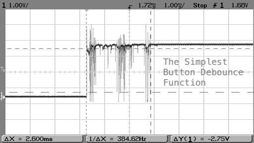
How could a false slip through? Knowing that the bounce is an unstable state over a time period (look at the graph top of page), the reads would need to match the rhythm of the bouncing, or have the luck, to read 8 times in a row right on a bounce peak wave.
Could this occur? Yes, but it’s unlikely; and the false state wouldn’t last for very long. Our mcu is very fast and may be able to take 10, maybe even 100 readings inside of a single millisecond. If a switch bounce phenomenon event lasts on average 1.6ms, or between 1 and 6 ms (source: http://www.ganssle.com/item/debouncing-switches-contacts-code.htm, section: Bounce Stats), to get a false reading we would need to make 8 readings in a row during a bounce event, each time reading the false state.
• if we can read 10 times per ms, and the bounce phenomena lasts 1.6ms. We can make 16 readings in this time. We need 8 of them *in a row* to have the same-incorrect value.
• if we manage 100 reads/ms, and the bounce is a whopping 6ms duration, that’s 600 readings! Again, we need to find 8-in-a-row with the same-incorrect-value.
As we near the final moments of the up-to-6ms bounce event, we are not going to see 50% chance of a H or T. Look again at a bounce waveform example… from a High to Low event, for the first half of the duration there are fewer High than Low values. For the remainder of the duration High values are dominating, which is exactly what we expect as per a bouncing ball.
Conclusion: Not only must we read 8 consecutive false states to obtain a false switch, as time proceeds there is greater likelihood of reading being true. Remember that the worst case scenario would be that at every reading there is a 50% chance of the reading being false. To obtain 8 such readings sequentially : 0.5^8 = 0.0039 (0.4%) and this has been obtained without hardware, in a handful of lines of code. Provided that the reliability of your button isn’t on par with an Apollo mission to the moon, how much more reliability must we demand before we can reasonably accept this this code is “pretty good” ?
Has anyone got this working with interrupt pins? I’m working with a custom prototyping board (similar in concept to the TinyLab. I have five pushbuttons (on my Mega port K, pin 1-5) and I’ve adjusted the code to work with hex addressing. However, I still have a headache with interrupts and can’t seem to get them working correctly.
Software debouncing is required because you don’t want to add hardware to your existing design. Since you are developing a custom board, looking at TinyLab design which has a weird button configuration circuit with both a pull-up and pull-down resistors, if you replace the pull-down resistor with a 1uF capacity(i.e. in parallel with the switch), you will have a RC hardware debouncing circuit, in fact, you don’t even need the pull-up resistor by using
pinMode(switch, INPUT_PULLUP)to configure the pin, it will give you a weaker roughly 47k internal pull-up!Haha sorry the TinyLab design was more of a sample of the form of board I’m using. The build that I’m using is custom for the program I’m taking at the polytechnic.
The pushbuttons I have are only on standard pullup – so the code functions perfectly – but I can’t add a 1uF capacitor (the PCB is already preeeettty crowded, and this has been in use by the program for several years now, so I am not in a position to be able to suggest a design revision).
So yes – still trying to figure out using this with an interrupt!
Thank you for this wonderfull script!
You work with pulling down the input for activation, I tried to convert the code for pulling up the input (as i in general work that way) but all attempts failed 🙁
My logic says to invert the BIN/hex numbers, meaning 0xfe00 becomes 0x01ff and 0xff00 becomes 0x00ff but this doesn’t seem to work 🙁
bool debounce() {
state = (state<<1) | digitalRead(btn) | 0x01ff;
return (state == 0x00ff);
}
Other attempts with Right shift in stead of left shift also doesn't work
Please help me?
If you are using high-side button, you need to comment-out the line
pinMode(btn, INPUT_PULLUP);or change it topinMode(btw, INPUT);.[Ashamed] Damn, I was changing too many/complex!
This makes you library/script even more beautifull! THANK YOU!!
Suggestion to expand your library with a PullUp/PullDown selection
How to use pin change interrupt instead of polling in the loop?
The provided code clearly is incompatible with deep sleep techniques.
Just because the code doesn’t use interrupt doesn’t means it is “incompatible”. Did yo tried to call the function within the ISR or better off setup the flag within the ISR to signified the button is pressed? Wakeup from deep sleep doesn’t need debouncing, it only need to be wakeup, debouncing is after wakeup if you need.
Finally, some sound engineering insight to the deluge of Arduino sketches and libraries that don’t seem to consider classic methods such as bit twiddling.
This debounce function can also be implemented with a simple counter instead of a shift register, which might simplify understanding, but it would require branching.
One thing to also note is that this debounce function only returns TRUE on the rising edge, rather than throughout the entire ON state of the input. To detect the falling edge, use the same debounce function but with the input negated. This will give you a stable source of ON/OFF events that you can then use to detect long presses.
This is a really interesting method of doing debounce. If you want to detect release you can use (state == 0xFE01) instead of (state == 0xFF00).
Nice routine!.. works a little different than I expected.. If switch is open (high, pullup), then routine returns all zeros.. When the switch is pressed, it returns one state of high, then returns all lows, even though the switch might remain pressed. This is quite different than a typical hardware debounce and might assume too much. It also doesn’t work quite like the hardware equiv shown. I would expect that it would work thus: Switch is open (high). read switch 4 times and then the debouce() returns high. Switch goes low. debounce will go low and stay low on 4th read.. (assuming the read is the “CLOCK” in the hardware equiv.) .. I am running this on Nano v3 (old).. maybe I missed something or is this how it was intended?
What do you think about this solution (edge detection / pressed / released):
uint8_t ev_pressed = 0;
uint8_t ev_released = 0;
static uint8_t shiftReg = 0;
shiftReg = ((shiftReg << 1) & 0x06) | buttonState | (shiftReg & 0x08);
if(shiftReg == 0x07)
{
ev_pressed = 1;
shiftReg = 0x8;
}
if(shiftReg == 0x08)
{
ev_released = 1;
shiftReg = 0;
}
Best regards
Martin
Thank you so much for this solution, Here my version of it.
bool ReadSwitchState(int PinNumber)
{
// Because the pin is in INPUT_PULLUP mode, the pin state is reversed,
// pressed = 0x0000, released = 0xffff.
uint16_t state = 0;
for(int i = 16; i > 0; –i) // This code execute in 9.0820us on a ItsyBitsy
{ // M4 SAMD51 @ 120kHz
state = (state << 1) | digitalRead(PinNumber); // Read pin state (0 or 1) and save as 16 bits in state
}
return(state == 0x0000); // true if depressed (ON) (0x0000), false for anything in between
// because the button is bouncing or release (OFF).
}
How can you make this work for release debouncing too? AFAIS it’s only for press action.
All of that looks fantastic and very exciting but you fail to explain the btn1.begin(2); and btn2.begin(3); lines?
What significance do the numbers 2 and 3 in the brackets have?
void setup() {
btn1.begin(2);
btn2.begin(3);
pinMode(LED_BUILTIN, OUTPUT);
}
I don’t think that I “failed” (that’s a strong word) in explain anything. Please read the paragraph before the code, or even better the entire section of “Handling multiple buttons”. 2 and 3 are GPIO pin2 for btn1 and GPIO pin3 for btn2.
You could have simply stated ‘For example, “btn1.begin(2);” configures what is assigned to be “btn1” to be physically attached to Arduino pin “2” as a GPIO pin to be an input pin with its internal pullup resistor enabled. The function “begin()” code is defined in file [button.h]. The main program calls “btn#.begin()” for each physically attached and defined btn# that is wanted to be used.’
Henry Cheung, Thank you for publishing this. Your improvement to Jack Ganssle’s debouncer is working fine on my attiny1616. It is a great solution for a non-blocking software debouncer.
Compact and reliable code! I again realize the fact that the simple is the best. Thank you very much for your share. From the other side of the globe.