Continue from previous article where I examines the RAK7243 Lora gateway, in this article I take a look at RAK5205. I like the RAK7243 but couldn't say the same for RAK5205 for several reasons...
RAK5205 LPWAN Tracker Board
The RAK5205 module has several built-in sensors and a 30-pin header that is compatible to the 96Boards, but the interface is the least concern when choosing a Lora sensor node or development board.
The core of the RAK5205 is another RAKWireless module RAK811 that comes as an SMD module with an RF-shielded enclosure. When you interface with or programming RAK5205, you are really dealing with RAK811, the RAK5205 board is just the board that hosted all the sensors on the board and provide an external interface header.
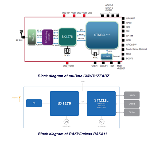
The RAK811 is based on Semtech SX1276 for (SX1278 is used for China region) chip for international market with a STM32L151CBU6 MCU. Architecturally, the RAK811 looks very similar to muRata module which is also based on SX1276 but with a different STM32L0x2 MCU when you compare it on the system block diagram level with RAK811 module.
Officially RAK5205 is called "RAK5205 LPWAN Tracker Board", the name implies that it was designed as a tracker for applications such as asset tracking and environmental tracking, and therefore come with a few related sensors, such as:
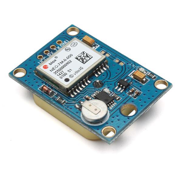
- Ublox Max 7Q GPS Module
- Bosch BME680 Environmental Sensor (Temperature, Humidity, Air Pressure, Gas)
- ST LIS3DH 3-axis Accelerometer
Internally all three sensors interface with STM32L1 via I2C interface, and the STM32L1 communicates with SX1276 via SPI. The 30-pin header exposes two UARTs, one I2C, one ADC and several GPIO pins including two pins that connect to user-programmable on-board LEDs.
To setup the RAK5205 and connect to The Things Network is quite trivia using AT commands so I won't talk about it here, you can follow the RAK5205 Quick Start Guide. For communicating with RAK5205 with AT commands, RAK suggests you to download RAK Serial Port Tool which is a Windows-only application, you don't have to use that particular tool, you can use Putty as well. Personally I'm on the macOS, so I just use my Arduino IDE's Serial Monitor to send AT commands to the RAK5205. For Linux, you can use minicom or picocom.
Things that I don't like the RAK5305
It seems that the RAK5205 built-in sensors are there for specific applications such as asset tracking or environmental monitoring. These sensors may not be relevant if your application is not related to asset tracking or environmental monitoring and therefore may seem useless other than demonstration purpose. Even some of those sensors are relevant to your application, you might not want to use it "as is". Here are a few reasons why...
1. Ublox Max 7Q cold start
RAK5205 uses the same GPS module as the one in RAK7243 gateway, the default software of the RAK5205 offers a sleep mode to keep the battery consumption low, this is an import feature and where the RAK5205 truly shine (more on this later).
The Ublox Max 7Q on the RAK5205 however does not has a back-up battery for the GPS module, so each time when the RAK5205 come out from sleep mode, the GPS basically has a "cold start", it takes 30-45 seconds for the GPS to get a GSP satellite fix for getting latitude and longitude data. A GPS backup battery would allow the GPS to have a "warm start" and the latitude and longitude data can then be obtained quickly. So if your application really need a GSP location, then you probably won't want to use the on-board GPS "as is" and would have to add the circuitry for backup battery, or better off to get one of those GPS modules that is commonly available on Amazon/eBay/AliExpress, as all those cheap modules have backup battery and EEPROM on board.
By default, the GPS on RAK5205 is turn on and have a time out setting of 60 seconds. If the GPS is unable to get a satellite fix within 60 seconds, the RAK5205 will display "GPS out of sync" error. Use the following command to change the gps_timeout setting:
at+set_config=device:gps_timeout:60
To turn of the GPS, run:
at+set_config=device:gps:0
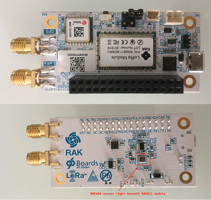
2. BME680 Sensor placement on PCB
BME680 sensor is probably the best-in-class environmental sensor from Bosch, RAKWireless made a rookie-mistake when designing the RAK5205 PCB by placing the sensor directly underneath the RAK811 Lora module. As the result, when you power up the RAK5205, the heat from the RAK811 quick heat up the BME680, making it 3 - 5 degree Celsius higher than the actual atmosphere temperature. Whoever design the RAK5205 board probably never read the Bosch's design guidelines. So again, you probably don't want or can't use the on board BME680 for your temperature measurement.
I did not test the accelerometer.
So in summary, it will better off to buy the cheaper RAK811 LPWAN Evaluation Board for your Lora project or build your own board with your own sensors based on your application with RAK811 LPWAN module.
3. The limitation of AT command interface
RAK5205 (or more precisely RAK811) provides a high-level user interface via AT Commands, those AT commands are sufficient for interacting with the sensors and configure the Lora module if you are intend to use the RAK5205 "as is" for your application deployment. The AT command set does not support customisation so there is no way to add new sensors or new features to the board without replace the existing firmware with your own firmware.
The AT command interface also means that you would need another host MCU to communicate with the RAK5205 instead of leveraging on the powerful STM32L1 chip to add features and functionalities. It would be much better to provide a lower-level SPI interface with well-defined APIs so that further development can be done with the on-board STM32L1 chip.
Many of the Lora development modules available in the market nowadays take the latter approach to provide lower level SPI interface with Lora chip (and LoraWAN) with the help of library such as IBM LMIC(LoraMAC in C) to enable the further development of Lora application.
One thing that I like about RAK5205
There is one thing that I like the RAK5205, that is its power consumption during sleep mode. RAK5205 does not has a dedicated power indicator LED, so when you power it up, you will only noticed a quick one-time blinking of the two on-board user-programmable LEDs, this is a design with intention for keeping the quiescent current of the board as low as possible when powering with a battery.
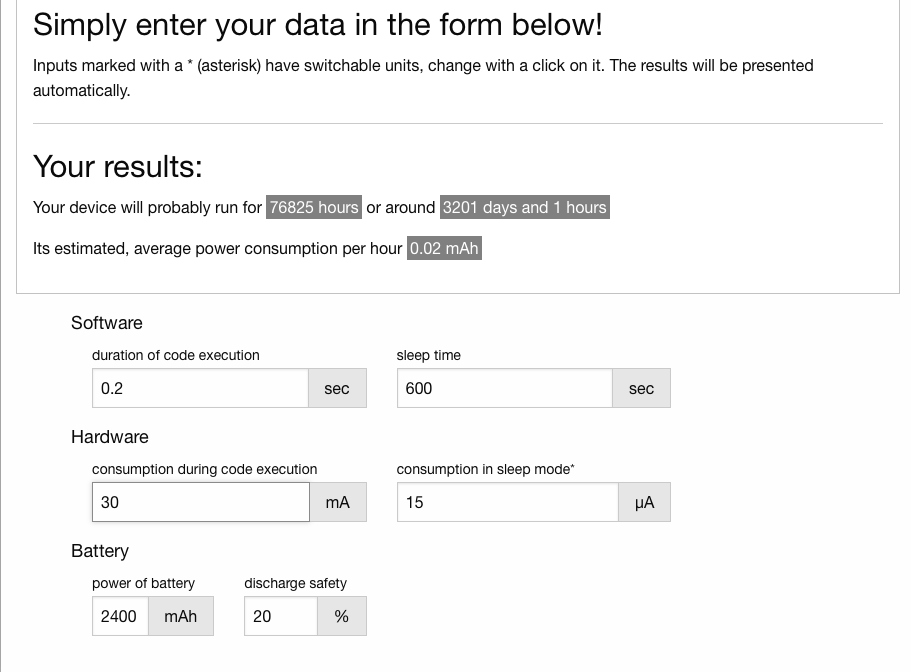
Based on the information from actual data log, each transmission take about 62ms, assuming there are some overhead in setup time, and sensor reading, etc. I assumed it will take a total of 200mS in wake-up mode. This is based on the assumption that GPS is turned off with the reason that I mentioned before. And in most of the sensor node applications (unless you are doing asset tracking), you don't really need GPS.
The published power consumption at sleep mode for RAK5205 is 14.6uA. RAK didn't publish the consumption power for RAK5205 during transmission, but RAK811 module specification shows it consumed a minimum of 30mA during transmission (the peak current could be as high as 120-130mA depend on power output), so if we assumed that the module only wake up in every 10-minute to take the reading of the sensors and send it to the gateway, and I plug in those assumptions into Battery Life Calculator, it shows that a typical 2400mAH 16500 battery will last for 3200 days (i.e. more than 8 years)!
Realistically, depending on the spreading factor you are using for your Lora network setup, your battery consumption could be much worst than this over-simplified battery calculation for Lora. The ratio of energy consumption per activity cycle is 20 times more energy for SF12 than SF7. Read how spreading factor affects LoraWan device battery life for details.
My unsucess firmware upgrade to support AS920
The AT command at+get_config=lora:status provides quite some information on how the Lora chip is provisioned, most of the parameters can be altered via AT commands. RAK5205's documentation only lists part of the basic AT commands, but a comprehensive list of AT commands can be found under the RAK811 documentation - RAK811 AT Command Manual.
result return from at+get_config=lora:status
*************************************************
==============LoRaWAN Status List================
Region: AS923
Send_interval: 30s
Auto send status: true.
Join_mode: OTAA
DevEui: 0000000000000000
AppEui: 0000000000000000
AppKey: 00000000000000000000000000000000
Class: A
Joined Network:false
IsConfirm: false
Work Mode: LoRaWAN
AdrEnable: true
EnableRepeaterSupport: false
RX2_CHANNEL_FREQUENCY: 923200000, RX2_CHANNEL_DR:2
RX_WINDOW_DURATION: 3000ms
RECEIVE_DELAY_1: 1000ms
RECEIVE_DELAY_2: 2000ms
JOIN_ACCEPT_DELAY_1: 5000ms
JOIN_ACCEPT_DELAY_2: 6000ms
Current Datarate: 5
Primeval Datarate: 5
ChannelsTxPower: 0
UpLinkCounter: 0
DownLinkCounter: 0
AntennaGain: 2.15
===================List End======================
*************************************************
The result indicates that my RAK5205 operates on AS923 instead of AS920, RAKWireless send me a new firmware build which according to RAKWireless that they had add the AS920 frequency table into the firmware. However, after re-flashing the board with the new firmware, I got an error message ERROR: RUI_AT_LORA_PARAMETER_INVALID 82 and AT command at+get_config=lora:channel shows that the frequency band is defaulted to EU868!
It seems that when flashing the new firmware using the STM Flash Loader Demonstrator, it erases the area where configuration parameters are kept in the flash memory. As the result, I will have to enter the configuration one by one via AT commands.
A quick search on the Internet indicated that the error RUI_AT_LORA_PARAMETER_INVALID 82 can be fixed by setting the join_mode and create a dummy device_eui, app_eui and app_key.
In order to change the frequency band, there is an AT command at+set_config=lora:region:xxxxx that I can use to "switch" the frequency band, however, the firmware does not accept AS920 as a valid input. It looks like that although RAKWireless add the AS920 frequency allocation table into this new build of the firmware, they forgot to change the AT command to accept AS920 as a valid input, so I'm back to where I begin, the RAK5205 with the new firmware can be configured to operate at AS923, but not AS920.
I was not getting any feedback from RAKWireless after more than a week of waiting so I chased for an answer. After a couple rounds of messaging exchanges, I was told that this will be fixed in next release but they are unable to provide a new test build for my test, citing busy project schedule, and no confirm date was given for when the next next official release is going to be.
RAKWireless' Development Environment?
So I'm stuck! I either throwing the RAK5205 into trash bin and call it piece-of-crap and be done for the day, or find a way to do it myself.
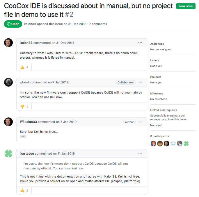
One of the obvious option is to compile the code myself based on the source code available on the RAKWireless GitHub. A quick look at RAK5205 User Manual V1.4 (Under section 6) shows that Coocox IDE is used for development with GCC ARM compiler. But the examples on RAK5205 github repository was based on Keil, and judging from the comments left by users of the github repository, I'm not the only one feel confuse!
It seems that over the past two years, RAK5205 not only switching its development environment setup twice, but the GitHub repository has been "abandoned" and never been updated since v2.x.1.10, while the current available firmware that you could downloaded from RAKWireless is v3.0.0.12!
The new firmware now also in favour of a new development environment that RAKWireless called RUI (Rak Unified Interface) - an SDK that provides hardware abstraction layer across different MCUs. In order to use RUI, you will have to upload your code to an web-based RAK online compiler to compile the code and use a separate tool to flash the binary to the device. This is cumbersome and impractical, I decided not even to give it a try.
Arduino-LMIC ecosystem
So what do to? My ultimate expectation is that I should be able to develop my Lora IoT application no matter what Lora module or board that I'm using. To me Lora should just be a transport stack for sending data from the remote sensor nodes to the gateway and I shouldn't spent too much time and trouble to deal with it.
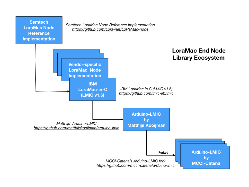
Semtech as the Lora technology inventor, provides a LoraMac node reference implementation, many Lora module/board vendors have their own Lora end node implementations, likely derived from Semtech's reference implementation. I briefly mentioned IBM LMIC library previously, LMIC stands for LoraMAC-in-C, and was originally developed by The IBM Zurich Research Laboratory, IBM has ceased the development of the library since 13-July-2015, but IBM made it available as open-source code under BSD license (same license as Semtech reference implementation). Since then, it has been port over to Arduino platform by Matthijs Kooijman, Matthijs' version has then been forked many times, and as the results there are many versions of Arduino-LMIC available nowadays on the Internet. Among all the forks, MCCI-Catena version of Arduino-LMIC maintained by Terry Moore remains the most active one, it also added the enhancement such as allowing new frequency plan to be added, and as the result supports most of the Lora bands as compare to Matthijs' version which only supports EU and US bands so far.
What Arduino LMIC does is enabling MCU to communicate with the SX1272, SX1276 transceivers and compatible modules (such as some HopeRF RFM9x modules and the Murata LoRa modules) via SPI interface. The Arduino platform provides the necessary HAL and common language APIs for interfacing with almost all the modern MCUs, such as STMicro's STM32 chips, Microchip's SAND ARM chips, Nordic chips and many more.
I decided to give it a try, within a few minutes, I'm able to replace the RAKWireless firmware completely and load my own sketch and everything seems to work perfectly! As this article is getting too long, I will talk about how to leverage Arduino-LMIC to develop Lora application on next article.
Summary
Overall, I like the RAK7253 but couldn't say the same for RAK5205. I think RAKWireless is a good hardware company but their software capability is not at the same level as their hardware capability. But even on hardware design, I've spotted a couple of issues on RAK5205 that shouldn't happen or could be done better.
Personally I prefer the RAK811 Evaluation board or RAK811 bare bone module than RAK5205 for the reasons that I mentioned above.
Obviously a board like RAK5205 with AT command interface offers limited capability for adding sensors, or doing further application development. Arduino-LMIC library together with Arduino platform offers a cross-platform development environment, tool chains and Hardware Abstraction across all modern MCUs to interface with Lora modules with Semtech chipset such as SX1276. I'm going to talk about how to leveraging Arduino LMIC for Lora application development in Part 3 of this series, stay tuned...