ATtiny3217 is a modern AVR microcontroller chip from Microchip that could potentially replace ATmega328p that is widely used in official Arduino boards, and here is how I build an Arduino compatible development board based on ATtiny3217.
ATtiny3217 versus ATmega328p
Recently when I browse Microchip's website trying to understand the differences between ATmega328p with another MCU, I came across the new tinyAVR 1-series MCU family, and particuarly ATtiny3217 that was released in 2018. It has almost all the features of ATmega328p that is widely used in Arduino Uno, Nano, and Pro Mini, and yet it offer more features that don't exists in the old ATmega328p.
TL;DR
Scroll down to the end of this article to watch the YouTube video.
Traditionally ATtiny family has low flash and SRAM memory size as well as low pin count, this has changed since the release of tinyAVR 0-series and 1-series MCUs in 2018. The ATtiny3217 is the highest in terms of memory and pin count within the tinyAVR 1-series MCU.
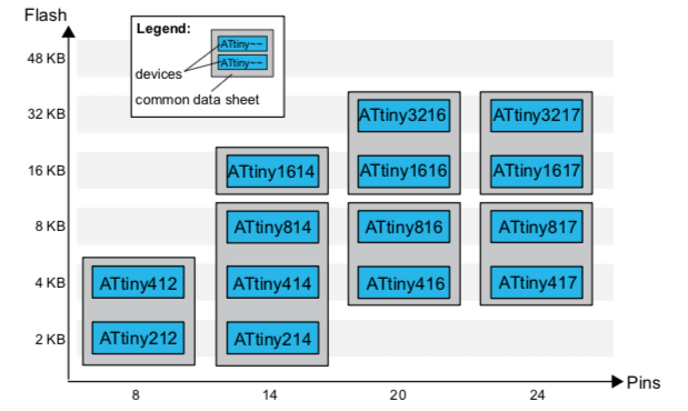
ATtiny3217 is a 24-pin MCU, yet it offers the same amount of flash memory and SRAM as ATmega328p, the only memory that is less than the ATMega328p is the EEPROM which has only 256 bytes compare to 1024 bytes in ATmega328p. The total programmable I/O pins of 22 is also almost the same as ATmega328p's 23 programmable I/O pins. Both MCUs have the same hardware UART, SPI and I2C port. The similarity end there, ATtiny3217 has 2 ADC, each with 12 channels of 8-bit ADC, versus ATmega328p of one ADC with 8 channels of 10-bit ADC. In terms of PWM capable channels, ATtiny3217 offers 8 PWM channels while only 6 pins are configurable for PWM in ATmega328p.
Differences between ATmega328p and ATtiny3217
| ATmega328p | ATtiny3217 | |
|---|---|---|
| Flash Memory | 32K Bytes | 32K Bytes |
| SRAM | 2K Bytes | 2K Bytes |
| EEPROM | 1K Bytes | 256 Bytes |
| UART | 1 | 1 |
| SPI | 1 | 1 |
| I2C | 1 | 1 |
| ADC | 1 | 2 |
| ADC Channel | 8 x 10-bit | 12 x 10-bit |
| PWM Channel | 6 | 8 |
| IO | 23 | 22 |
| Timer |
2 x 8-bit 1 x 16-bit |
1 x 16-bit(Type A) 2 x 16-bit (Type B) 1 x 12-bit (Type D) |
There are several notible features that are not available in ATmega328p, such as:
- Three 8-bit DACs with 1 external channel
- Configurable Custom Logic/Lookup Table
- 16-bit Real-time Counter
- 6 Event System Channels
- Periperral Touch Controller
- 5 Configurable Internal Voltage References (versus ATmega328p's 1 at VCC level)
Maybe it is time to replace the old Arduino with an ATtiny3217-powered Arduino?!
ATmega328p doesn't have any DAC while ATtiny3217 offers 3 8-bit DAC channels. Configurable Custom Logic/Lookup Table is an interesting feature, let's say you are designing a circuit and you realised that you would need a flip-flop circuitry, instead of rushing to your component store to get a flip-flop IC, you could configure a flip-flop within ATtiny3217. ATtiny3217 offers more timers with 16-bit, it also has a 16-bit build-in real-time clock derived from the interal clock source. Another powerful feature is the event system channel that allows you to tie the output of one event to trigger the input of another channel without involved CPU process. All the modern MCUs release in the past 10 years or so comes with Periperral Touch Controller, and there is no except for ATtiny3217. Five configurable interval voltage references make the measurement of analog input easier and potential save the needs of having an external voltage regulator chip in case you need a reference voltage, say, 1.1v.
All in all, this make me thinking that maybe it is time to replace the old Arduino with an ATtiny3217-powered Arduino?!
ATtiny3217 Arduino-compatible Development Board
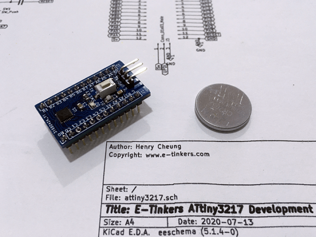
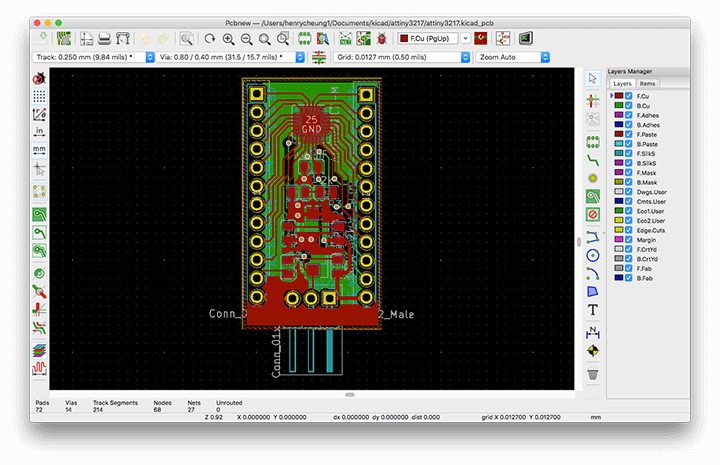
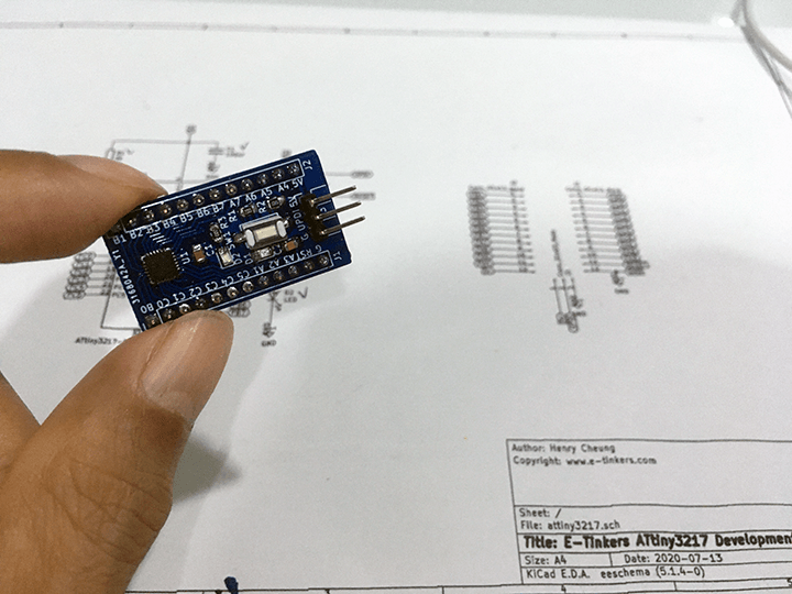
In order to use ATtiny3217, you almost always have to have some sort of break-out board because ATtiny3217 is really tiny and only come with 24-pin VQFN package. So I uses KiCad to create the schematic and do the PCB layout. The result is a tiny breadboard-friendly PCB of only 34.6mm * 19.3mm in size.
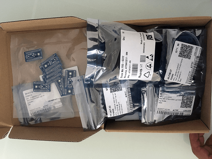
When everything looks okay, I placed an order for producing the PCB. The PCB manufacturing took less than 72 hours to complete and shipment took about a week to reach me.
It is a little bit unreal to hold an Arduino compatible board designed by myself, and I can't wait to see it will actually work.
Install MegaTinyCore
In order to use the ATtiny3217 development board as an Arduino, we will need an Arduino Core software, luckily Spence Konde has done great works in the past a couple years to create a megaTinyCore that supports tinyAVR series including ATtiny3217.
Follow the installation instruction on Spence Konde's github repository to add the url for board manager json file to the Arduino IDE preference.
http://drazzy.com/package_drazzy.com_index.json
Next click on Tools -> Board -> Board Manager, and search for "megaTinyCore", and click on install to install the megaTinyCore on your Arduino IDE. The installation took a couple of minutes to complete.
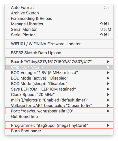
I can now select the ATtiny3217 board from the Tools -> Board pulldown menu, double check to make sure that I select the correct chip, port and set the programmer as "jtag2updi(megaTinyCore)".
UPDI Programmer
All the modern AVR chips uses Unified Program and Debug Interface (UPDI) interface for uploading the code on to the MCU. UPDI is a single-wire interface providing a bi-directional half-duplex asynchronous communication with the target device for purposes of programming and debugging.
The jtag2updi is a project originated from ElTangas that turns an Arduino Nano (You could use an Uno or Pro Mini as well) into a UPDI programmer. I used the fork version from Spence Konde as it seems to be optimized and more up-to-day.
To turn an Arduino Nano into a UPDI programmer is easy, download the firmware from Spence Konde's jtag2updi github. cd jtag2updi into the directory and double-click on jtag2updi.ino sketch file to open it on Arduino IDE. The sketch itself is empty, but you will see all the .cpp files that are needed to be compiled in different tabs. Click on "upload" button on top of the Arduino IDE to upload the firmware to the Arduino Nano.
To connect the UPDI programmer(Arduino Nano) to ATtiny3217 board, you will need a 4.7k resistor and 10uF capacitor. Connect the 10uF capacitor between RST pin and GND of the Arduino Nano, connect the 4.7k resistor between I/O pin 6 of Arduino Nano and UPID pin on the ATtiny3217 board header.
Programming the ATtiny3217
We are all set to program the ATtiny3217 board, I'm excited to see if all my works will pay off and the board actually work properly!
When power-up, the RED power LED indicated that there is no short-circuit or anything like that. The board has an on-board Blue LED that is connect to Port A Pin 7 (PA7) of the ATtiny3217, we will write a blinking LED sketch to test it.
I created a blinking LED sketch, and click on upload. Everything went well, the UPDI seems to be quite fast, there is an avrdude error message at the end of flash status screen, but that's seems to be harmless as the BLUE LED already start blinking!
I'm not alone
Now I have my own creation of an Arduino compatible board. I must say that I'm not alone, before I started my project, I did my research on similar projects based on ATtiny3217, and I found two different boards selling on tindie.com, including the one produced by Spence Konde(a.k.a. Dr Azzy)who is the creator of of megaTinyCore, and another one by LeoNerd. I also found a video on YouTube from Dustin Watts talking about his design. There is also a design done by Albert van Dalen. I actually change part of auto reset after seeing his implementation.
Summary
There are much to explore for this new and much modern AVR chip. Such as Event System and Configurable Custom Logic, I'm sure those will bring new ideas and capability into the world of Arduino programming. Personally, I feel strongly that it is time to phase out the class AVRs such as ATmega328p and replace it with modern AVR series, as it is not only more flexible but atually cheaper!
Since I have ordered more components than I need for my personal usage, I intend to sell this ATtiny3217 Arduino Development Board in near future, once I sort out all the logistics for order fulfilment. In the mean time, if you are interested to have one, leave a comment below and I will be in contact when it is ready.
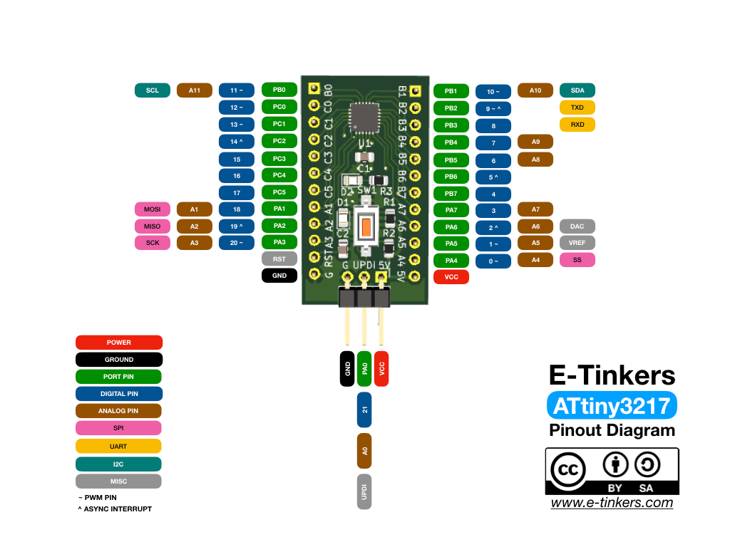
E-Tinkers ATtiny3217 Development Board Pinout
Great to see it worked out. I would say to build a real PCB including MCU/Arduino Module along with other customized peripheral components is much easier thsese days by asking PCB manufacturer to build PCB for you.
Soldering SMD parts with soldering iron is nightmare…I would suggest you to buy a soldering tool with both iron and hot wind, so you could inject soldering cream onto pad by needle and sold SMD parts by hot wind gun…Your electric life will be easier…
Hello
Do you already test 8pwm in same time?
What is the pin please?
Thanks
I just updated the post to add a pinout diagram which shows all the PWM pins. This is based on megaTinyCore and my board design.
Hi, an old issue of elektor electronics which should now be public domain, gave the specs for a DIY SMD oven, originally as a method of repairing or upgrading surface mounted chips within PC hardware. The oven should work as is and allow you to prepare whole batches of boards in one go.
I am inbetween computers for the next two weeks so cannot run
keyword search on my digital archives, but i will check through my hardcopies of the magazine and if i find it i will post the reference if not the article.
Dan,
I made a hotplate reflow with a preheader (those used for LED repairing), see my post https://www.e-tinkers.com/2021/07/converting-uyue-preheater-into-a-solder-reflow-hot-plate/.
Please look at my invention of a Combined FTDI / UPDI program connector for the ATtiny3217
https://avdweb.nl/arduino/attiny3217/ftdi-updi-connector
Albert,
Thanks for stopping by. I read your web page many years ago and aware of your invention, good to see the latest development on your connector. Personally, I never use the boot loader and have developed my own SerialUPDI+UART with auto-switching(with two lines of codes) between UART and UPDI mode with a 2×3 header.