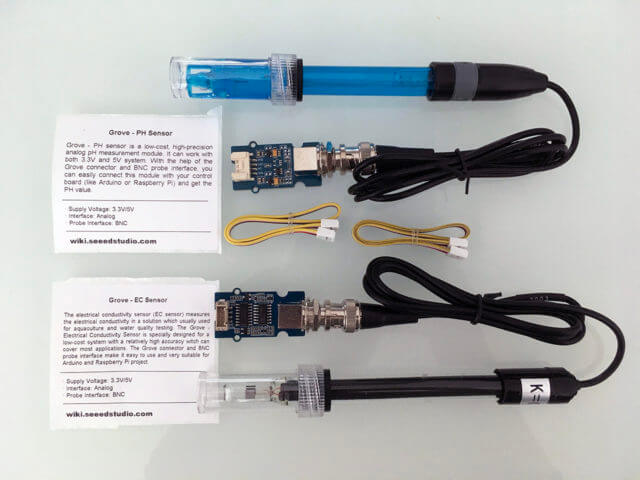
This is the second part of the two-parts review on Seeed Studio's ph and EC Sensor Kits. In this part, I will take a closer look at EC Sensor Kit and how to measure EC with an Arduino.
What is Electrical Conductivity(EC)?
Electrical Conductivity (EC) is the reciprocal of the resistivity, which is related to the ability of the material to carry the current. In the liquid, the conductivity represents the ability of the liquid to conduct electricity between two electrode contacts, due to the amount of iron disolved in the liquid. Such dissolved ionic substances vary depend on the type of water solution, such as salt concentration, or different minarals in the water, and therefore have been used for various industries and laboratory applications, ranging from water quality where the conductance represents the purity of the water, to hydroponics where the conductance changes due to the combination of the nutrients/minerals used for feeding the plants.
Conductivity is usually measured in micro-siemens or milli-siemens per centimeter (uS/cm or mS/cm). Conductivity is the conductance (S) measured across a specified distance (1 cm), which is incorporated into the units (S/cm). If you apply a voltage across two carefully-placed metal conductors seperated in a distance, as long as the temperature and composition remains the same, the conductivity of water will not change and can therefore be observed.
Conductivity (G) is the reciprocal of the electrical resistivity (R):
G = 1 / R
The ratio of the distance (l) and area (A) of the conductor plate is called Cell Constant (K).
K = l / A
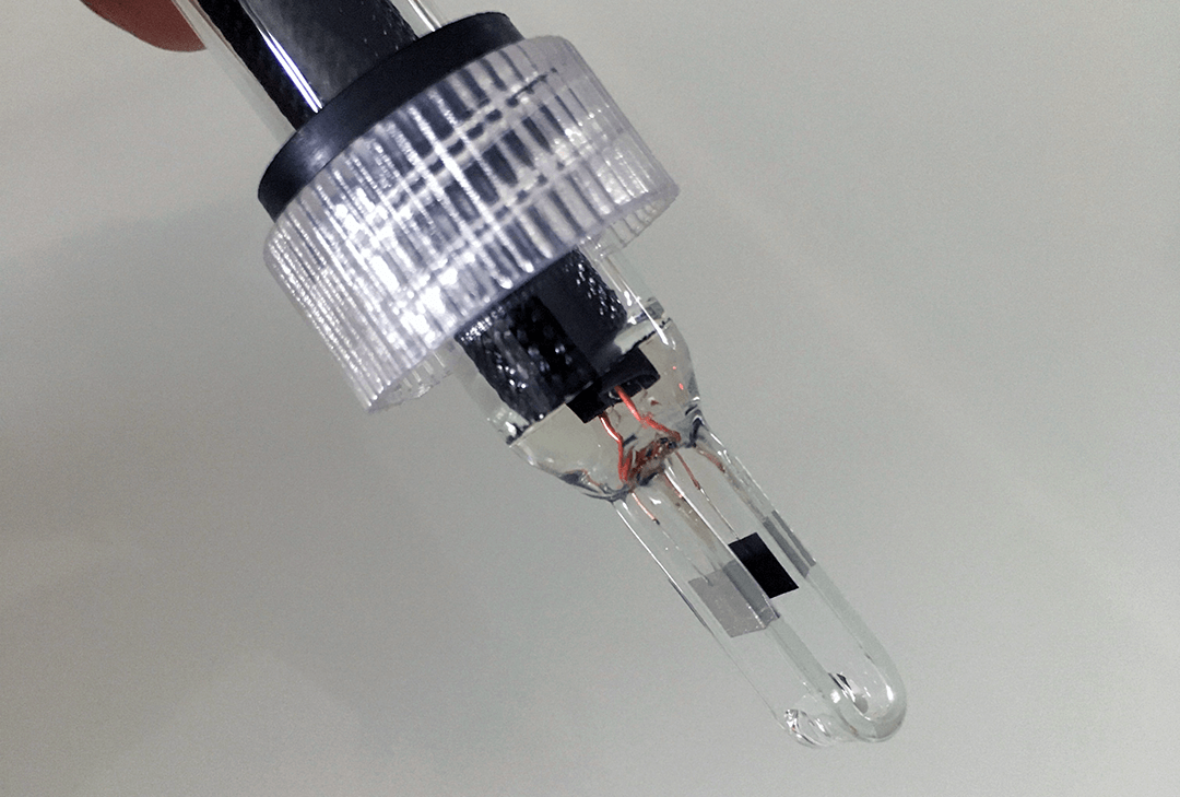
The Cell Constant is usually marked on the EC Electrode, and usually have a Cell Constant of K=1 or K=10, which type of Electrode to be used depend on type of applications (such water purification, or waste management) and concentraion of the dissolved ironic substances in the solution.
This is the basic concept of how an EC electrode works and how it is designed. If you look at an EC Electrode, you see two conductor plates sepearated at a distance that both the area of the plates and the distance between the two conductors are carefully calibrated.
The standardized conductivity is the conductance at a given Cell Constant:
k = K * G
or
k = K / R
Electrical conductivity is also sensitive to temperature change, and gradually increases in a metallic conductor as the temperature is lowered. As we learnt in secondary school physics study, below a critical temperature, resistance in superconductors drops to zero, such that an electrical current could flow through a loop of superconducting wire with no applied power.
EC electrodes is an active sensor that requires an excitation voltage to be applied to get the result. When A DC voltage is apply to the two conductors, it caused iron to be flow from one conductor to another, causing polarization and chemical reaction. In order to avoid polarization, an alternative current (AC) typically ranging from 1kHz to 20kHz is used to provide the exitation of the electrode. The AC current is read and converted back to a DC voltage as the measurement result.
You can read more about Conducitvity Theory and Practice and Conductivity Measurement Theory Guide for more in-depth explanation behind various measurement methodologies and theories. Andy Connelly's blog Conductivity of A Solution is another great resoruce for the subject.
Seeed Studio EC sensor kits
There are many ways to measure EC, but most common way of measuring EC that I found on the Internet can be traced back to a design described in September 1977 issue of Electronics magazine on an article "One-chip conductivity meter monitors salt concentration" by Michael Ahmon. Ahmon's design concept seems to have been the basis for many of the EC sensor boards design available on the Internet, and there is no exception for Seeed Studio's design.
Michael Ahmon's Sept 1977 Article on Electronics magazine was originally hosted on a website until somewhat a year ago when the website closed down. I managed to find it from Internet Archieve and decided to keep an copy on my website.
The schematic of Seeed Studio's EC sensor board can be found from its wiki page.
Seeed Studio EC sensor board has an on-board XC6206 3.0v LDO regulator that take a 3.3 - 6v input and regulate it down to a stable 3.00v to drive the LMV324. In order to generate a truly AC current that is required to drive the EC electrode, a TPS60400 voltage inverter is used to generate a -3.0v so that LMV324 can operate at +/-3.0v.
Unlike Ahmon's design where a Wien bridge oscilator is used to generate an alternative current(AC) waveform for the excitation of the EC eletrode, Seeed Stduio's design utilized a CD4060 CMOS oscilator to generate a 20kHz AC current, it then attenated down to 200mV to drive the EC electrode. The AC current pick-up by the electrode and go through an Inverting Op Amp by an LMV324 chip. The Vin of the circuitry in this case is the voltage that coming from the oscilation circuit that we just mentioned and is remain a peak value of 200mV, the Vout of the circuit for an inverting op amp circuit can be derived from this formula:
Vout = Vin * (Rf/R), or
R = Vin * Rf / Vout
Where the feedback resistor Rf is shown as R2 on Seeed Studio's schematic and have a value of 820 ohm, and R is the resistance of the electrode when emerging in a solution. As mentioned before that the standardized conductivity is the conductance at a given Cell Constant:
k = K * G, or
k = K / R
and since:
R = Vin * R2 / Vout
therfore:
k = K / (Vin * R2 / Vout)

k = K * Vout / (Vin * R2)
So as you can see that Vin is 200mV and R2 is 820 ohm, K is the Cell Constant of the Eelectrode, If all those values remain constant, the conductivity of a solution is then directly proportional to the Vout.
Since the Vout is an AC voltage, in order to capture the peak value of Vout, it is then feed into a precision rectifier that capture the peak of the AC Vout and further filtered with a low-pass filter to get a DC voltage that is linearly propotion to the conductance of the solution that the EC electrode in contact with. This form the basic design of the Seeed Studio's EC sensor board deisgn.
Measuring EC with Arduino
Seeed Studio uses the Arduino library DFRobot_EC from DFRobot for calibration and measurement. The DFRobot_EC library comes with a example program called DFRobot_EC_Test.ino which requires a temperature sensor to be used in conjection with the EC measurement, it however doesn't provide the implementation of temperature sensing and leave its for users to implement it themselves. This is understanderable as temperature sensors come with all shapes and using different protocol (1-wire, I2C, etc.) and technology (analog thermister, digital thermometer, etc.).
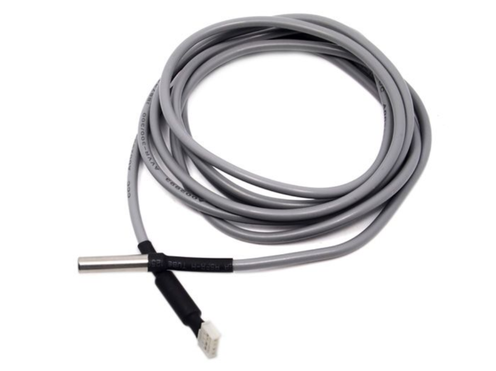
Personally I prefer DS18B20 1-wire Digitla Thermometer as it utilizes 1-wire protocol and has a form factor that is suitable for submerging into water available, making it easy to be interfaced with an Arduino. If you are buying a DS18B20 from other sources or already have an DS18B20, please noted that you will need to add a resistor (2.2 - 4.7k) between the input pin and the VCC (3.3v or 5v). Seeed Studio has a DS18B20/ SKU that alreay has a resistor soldered and wrapped into the cable assembly with a Grove connector and priced quite reasonably at US$7.50.
Here is the example code based on DFRobot_EC_Test.ino with DS18B20 digital themometer for temperatue compensation calculation. You may need to download and install OneWire and DallasTemperature Arduino libraries using Library Manager before compiling the code.
/*
 * file DFRobot_EC.ino
 * @ https://github.com/DFRobot/DFRobot_EC
 *
 * This is the sample code for Gravity: Analog Electrical Conductivity Sensor / Meter Kit V2 (K=1.0), SKU: DFR0300.
 * In order to guarantee precision, a temperature sensor such as DS18B20 is needed, to execute automatic temperature compensation.
 * You can send commands in the serial monitor to execute the calibration.
 * Serial Commands:
 *   enterec -> enter the calibration mode
 *   calec -> calibrate with the standard buffer solution, two buffer solutions(1413us/cm and 12.88ms/cm) will be automaticlly recognized
 *   exitec -> save the calibrated parameters and exit from calibration mode
 *
 * Copyright   [DFRobot](http://www.dfrobot.com), 2018
 * Copyright   GNU Lesser General Public License
 *
 * version  V1.0
 * date  2018-03-21
 */

#include <DFRobot_EC.h>
#include <EEPROM.h>
#include <OneWire.h>
#include <DallasTemperature.h>

#define EC_PIN A1         // Using A1 as analog input for EC electrode
#define SENSING_INTERVAL 1000

#if ARDUINO_ARCH_STM32    // for STM32 with 12-bit ADC

#define ADC_REF 3300
#define ADC_STEPS 4096.0
#define TEMP_PIN PB9      // Using pin PB9 as temperature sensor input

#else                     // For AVR Adrduinos with 10-bit ADC

#define ADC_REF 5000
#define ADC_STEPS 1024.0
#define TEMP_PIN 3        // Using pin 3 as temperature sensor input

#endif

DFRobot_EC ec;
OneWire oneWire(TEMP_PIN);
DallasTemperature ds18b20(&oneWire);

void setup() {
  Serial.begin(115200);
  ec.begin();
  ds18b20.begin();
#if ARDUINO_ARCH_STM32
  analogReadResolution(12);
#endif
}

void loop() {
  static unsigned long timer = millis();
  float voltage;
  float temperature;

  if(millis() - timer > SENSING_INTERVAL) {
    timer = millis();
    voltage = analogRead(EC_PIN) / ADC_STEPS * ADC_REF;
    ds18b20.requestTemperatures();                     // send command to get temperaure reading
    temperature = ds18b20.getTempCByIndex(0);          // reading temp in celsius
    float ecValue = ec.readEC(voltage,temperature);    // convert voltage to EC with temperature compensation
    Serial.print("temperature:");
    Serial.print(temperature,1);
    Serial.print(" C, EC:");
    Serial.print(ecValue,2);
    Serial.println("ms/cm");
  }
  ec.calibration(voltage,temperature);
}
There are a few nice things about the DFRobot_EC lirary:
- It implemented a Serial State Machine for user to entering and exiting calibration mode by typing a command from the Serial Monitor, this eliminated the needs for running a seperate sketch just for calibration and another sketch for measuring EC;
- It saves the calibrate results in the EEPROM;
- If you are using in conjunction with a temperature sensor such as DS18B20, the EC reading is temperature-compensated with the built-in formula in the library.
By default when you powering up the EC sensor board, it will running in the measurement mode. To calibrate the EC Electrode, you can type in the followng commands to activate, calibration and exit the calibration mode:
- enterec - Entering EC calibration mode;
- calec - Start calibration;
- exitec - Save the calibrated value and exit the calibration mdoe.
Note: The commands are not case-senstive.
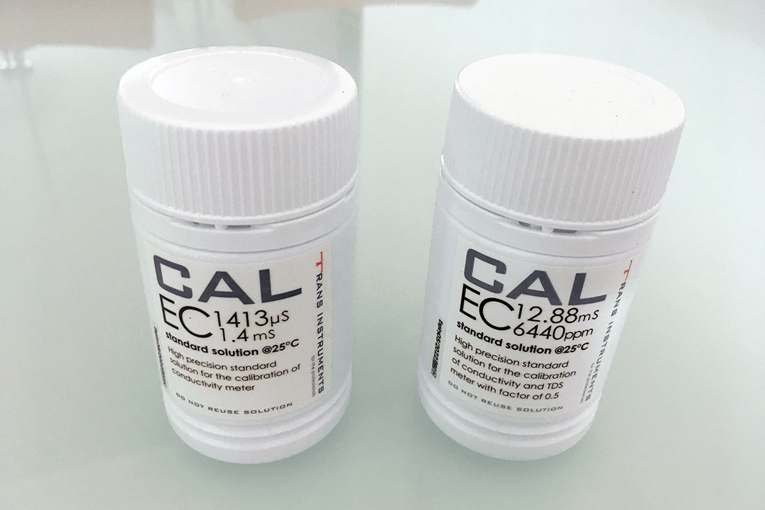
Seeed Studio recommends to use two standard buffer solutions of 1413uS/cm and 12.88mS/cm for two-point calibration. I purchase my buffer solutions locally as those can't be purchased online from overseas and ship via air transport.
The whole calibration process is quite simple:
1) Enter enterec on the Serial Monitor;
2) Put the electrode into one of the buffer solution, and enter calec to get the calibration done;
3) Enter exitec to exit the calibration mode;
4) Repeat the same step 1 to 3 for the second buffer solution calibration.
The temperature compensation algorithm has been integrated in the DFRobot_EC library. The readEC (float voltage, float temperature) method return the EC value with temperature compensation.
The DFRobot library use a hardcoded temperature coefficient formula as:
temperature coefficient = 1 + 0.0185 * (temperature - 25)
Many of the applications suggest of using a factor of 0.0191/degree Celsius (theritical value is 0.02) instead of 0.0185, if you want to make change of this factor, you will have to modify the library.
Laboratory Grade Electrode
The EC Electrode that come with the Seeed Studio EC Sensor Kit is a laboratory-grade Electrode, and Seeed Studio does not sell any Industrial grade electrode. The electrode is not designed for immersing in liquid 24/7. Get an Industrial-grade Electrode (which itself could be as much as 10x of what you paid for this sensor kit) if you need to use it 24/7.
Even you have an Industrial-grade Electrode, The sensor board does not provide a way to shut it down when it is not in measuring, so a constant exitation is apply to the Electrode. One easier way is to use a control pin from your MCU to cut off the board power supply when you are not measureing the EC. Of course, this will require some extra hardware circuitry. This will prolong the lifespan of your Electrode as well as reduce the polarization developed between the metal plates on the electrode.
Data stored in EEPROM
If you are using buffer solutions other than 1413uS/cm and 12.88mS/cm for calibration, you will need to modified the DFRobot_EC library code as those values are hard-coded in the formulas used in the library.
If you use EEPROM for keeping data in your previous Arduino project, make sure your read out those data or keep it in the memory locations that are not in conflict with EC Sensor application. DFRobot_EC library only uses 8-byte for keeping two floating point values starting at address 0x0A of EEPROM. In case you want to read out the values stored in the EEPROM for any reason, you can do so with this simple sketch.
#include <EEPROM.h>
#define KVALUE_ADDR 0x0A
float k1, k2;

void setup() {
    Serial.begin(115200);
    Serial.println();
    EEPROM.get(KVALUE_ADDR, k1);
    EEPROM.get(KVALUE_ADDR+4, k2);
    Serial.print("K Value at buffer 1413uS/cm: ");
    Serial.println(k1);
    Serial.print("K Value at buffer 12.88mS/cm: ");
    Serial.println(k2);
}
void loop() {
}
Working with Raspberry Pi
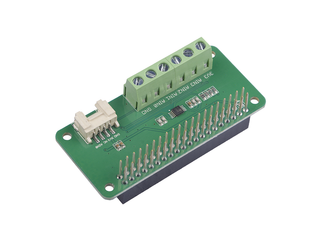
As Seeed Studio's EC sensor board is an analog sensor and Raspberry Pi doesn't have any analog GPIO pins for handling analog sensor data, therefore it is not possible to interface the Seeed Studio EC sensor kit directly with a Raspberry Pi. However, the DFRobot_EC library comes with a Python example code for using the EC sensor board with Raspberry Pi and an external ADS1115 16-bit 4-channel ADC, making it possible to interface with a Raspberry Pi via an external I2C interface. Seeed Studio has an ADS1115 Shield for Rapsberry Pi that seems to be a good fit for the purpose. Personally, I have not test the ADS1115 Shield yet as I don't have a one with me.
Summary
Seeed Studio EC sensor kit provided a reliable, easy to use and cost-effective solution for measuring EC with an Arduino or any compitable MCU development boards. It works well with both 3.3v and 5v MCU boards. The DFRobot_EC library hide the implementation complexity and can automatically detect standard buffer solutions used for calibration, and making both measurement and calbrition easier with simple Serial Monitor commands.
Thanks for this very informative article. I am interested in looking more into the background and would like very much to read the article “One-chip conductivity meter monitors salt concentration” by Michael Ahmon. Unfortunately your link comes up with a 404 not found error. Is the link broken or did you have to remove it for some reason? Is it still possible to get a copy?
Thanks for letting me know about the broken link, I have fixed it just now, in case your browser cache the old link, here is the link to get the pdf https://www.e-tinkers.com/wp-content/uploads/2020/07/one-chip_conductivity_meter_by_Michael_Ahmon_Sept_1977_Electronics.pdf.
Hello, I’m from Vietnam , i want to buy one but “Out off stock”. How can i get?