LCD 5110 (a.k.a. Nokia 5110 or PCD8544) display is a commonly available LCD module with SPI interface, by writing our own LCD driver based on its data sheet, we could learn a lot about how the LCD module works and how to write SPI program and save a lot of SRAM memory.
LCD 5110 with Arduino
LCD 5110 is often called Nokia 5110 display as it is used in Nokia 5110 mobile phone many years ago. It has an internal LCD controller PCD8544 from Philips, so it is also known as PCD8544 LCD display. The display has 48 rows x 84 columns of pixels with low power consumption and be able to operate from 2.7v to 5v, so it is very suitable for using in embedded application or interfacing with Arduino and Raspberry Pi. The LCD 5110 display module uses SPI (Serial Peripheral Interface) communication protocol, so it is also a good way to learn on how to use SPI library and have better understanding on how the SPI works.
The LCD 5110 that I purchased comes without any data sheet or instruction. I found the data sheet for PCD8544 Controller Datasheet form Philips with a quick search on the internet. The data sheet provides a lot of detail information for hardware design engineer and developer to integrate the LCD module into final product, I will just provide a high-level, condensed summary on the relevant information that is required to write our LCD driver.
Connections of LCD 5110 module
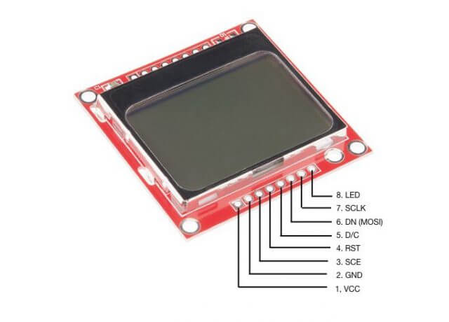
The LCD 5110 display module uses SPI (Serial Peripheral Interface) communication protocol, the name of each connection pin is marked on the back of the LCD module as show below.
| LCD | Arduino(Nano) | Function |
|---|---|---|
| 1. VCC | 5V | +VCC Power Supply from 2.7 – 5v |
| 2. GND | GND | Ground |
| 3. SCE | SS | SPI - Slave Select(SS), System Chip Enable when SCE=LOW |
| 4. RST | RST | Reset the chip when RST=LOW |
| 5. D/C | D8 | Command(D/C=LOW)/Data(D/C=HIGH) mode |
| 6. DN/MOSI | MOSI | SPI - Master Output, Slave Input (MOSI) |
| 7. SCLK | SCK | SPI - Serial Clock (SCK) |
| 8. LED | D7* | LED=HIGH, turn on back light LED |
- Connect to D7 via a 330 ohm resistor.
How to interface LCD 5110 with Arduino
I uses an Arduino Nano to interface with LCD 5110 module. Arduino has pre-defined constants for SPI SS (Slave Select), MOSI (Master Output, Slave Input), MISO (Master Input, Slave Output) and SCK (Serial Clock) pins and the actual pins assigned for those constants depend on different MCU the board used. It is safer and easier to always use those pre-defined constants when using the SPI Library. In the case of Arduino Nano (and all ATMega168/328P-based Arduino boards), for example, Arduino's pin 13 is designated for SPI's SCLK, and pin 11 is designated for MOSI. For the rest of the pins we can use just about any I/O pins. Since we only write data to the LCD module, therefore we don't use the MISO pin when communicating with an LCD module. The RST pin for the LCD module can be connected to the Arduino RST pin so that when Arduino is reset, the LCD module is also get reset. So other than the 3 SPI pins, we will need two extra pins for LCD Command/Data mode selection, and LED backlight control.
PCD8544 commands
Before data can be sent to the display, it requires to initialise the LCD with a few commands.
There are two sets of Commands: 1) Extended command set are those used to set up the operating conditions of the LCD, such as contrast, viewing angle, etc.. 2) Basic (or Normal) command set are used to setting the display mode and addressing position prior display data to be transferred. The initialisation and the usage of the commands in the Table 2 shows the steps we need to setup the LCD. I get those information by reading the data sheet, particularly from page 14 of the data sheet.
| Command | Binary Value | Description |
|---|---|---|
| Extended Command | 00100001 | Set to EXTENDED command mode (Chip activated, horizontal addressing) |
| Vlcd Voltage | 10110010 | Set Vlcd (Contrast) to 6v |
| Voltage Bias | 00010011 | Set voltage bias (viewing angle) to n=4, 1:48 |
| Basic Command | 00100000 | Set to NORMAL command mode |
| All Pixels ON | 00001001 | Turn on all pixels |
| Display mode | 00001100 | Set display to Normal mode |
| Addressing Y | 01000yyy | Addressing row with yyy |
| Addressing X | 1xxxxxxx | Addressing columns with xxxxxxx |
Setup PCD8544 via SPI library
The SPI library make the communication between master host (in this case Arduino) and slave (the LCD module) really easy. The spi.begin() set SCK, MOSI, and SS to OUTPUT mode so we don't need to call the pinMode() function to setup those pins. It is also pulling SCK and MOSI LOW and set SS HIGH if you are using Arduino boards. For non-Arduino boards such as ESP32, it might not set SS HIGH, so we can add the pinMode(SS, OUTPUT) to make sure SS will be set HIGH.
#include <SPI.h>

const int DC = 8;
const int BACKLIGHT = 7;

const int CMD = LOW;
const int DATA = HIGH;
const int ON = HIGH;
const int OFF = LOW;

void setup() {
    pinMode(DC, OUTPUT);
    pinMode(BACKLIGHT, OUTPUT);
    pinMode(SS, OUTPUT);
    digitalWrite(SS, HIGH);

    SPI.begin();    //set SCK, MOSI, and SS to outputs, pulling SCK and MOSI low, and SS high
    _write(CMD, 0x21);  // Set Extended Command set
    _write(CMD, 0xb2);  // Set Vlcd to 6v (LCD Contrast)
    _write(CMD, 0x13);  // Set voltage bias system 1:48 (Viewing Angle)
    _write(CMD, 0x20);  // Set Normal Command set
    clear(); // Clear all display memory and set cursor to 1,1
    _write(CMD, 0x09);  // Set all pixels ON
    _write(CMD, 0x0c);  // Set display mode to Normal
}
Writing Command or Data to PCD8544 via SPI
The SPI.beginTransaction() gains exclusive access to the SPI bus, and therefore it is important to release it after data transfer with SPI.endTransaction().
void _write(const uint8_t mode, char data) {
  SPI.beginTransaction(SPISettings(16000000, MSBFIRST, SPI_MODE0));
  digitalWrite(SS, LOW);
  digitalWrite(DC, mode);  //HIGH = Data mode, LOW = Command mode
  if (mode == DATA & _inverse == ON) {
      data = ~ data;
  }
  SPI.transfer(data);
  digitalWrite(SS, HIGH);
  SPI.endTransaction();
}
During each SPI clock cycle, Arduino (Master) sends a bit on the MOSI line and the slave (LCD) reads it, so we need to setup two thing before this can be transmitted. The SPISettings(16000000, MSBFIRST, SPI_MODE0) create an configuration object that specifies how the slave is expecting the SCK to be sent for data capture during the data transfer. The value 16000000 is the CPU clock speed of a typical Arduino board, it represented the max speed that the SPI device could operated. The MSBFIRST specifies whether the MSB or LSB to be sent first. What values that we need to pass into the SPISettings() object can usually be found in the data sheet of the slave device that the master is communicating with. Fig. 10 on the data sheet page 13 shows that the LCD module is expecting to receive the MSB first, and the data is captured on the rising edge of the SCK cycle from LOW to HIGH. SPI_MODE0 in the SPI library match the mode described by the LCD module.
Writing command or data into the PCD8544 Display Data RAM (DDRAM) is a matter of signalling the controller with proper control signals and sending the command or data using SPI.transfer() function. SPI is a bus structure, it means that all the slaves on the bus share the same SCK and MOSI/MISO lines, only be addressed individually by the SS signal. So when we want to communicate with the LCD module, we first need to set SS to LOW to signal the LCD module that we want to send data over, and turn off the SS line after the data transfer by setting the SS to HIGH. The D/C pin will remain LOW when sending the commands, and only be HIGH when display data is transferring to the RAM.
PCD8544 provide a command that allows to set the display in Normal display mode (i.e. black pixel over white background), or Inverse mode (i.e. white pixel over black background). This command provide a screen-wide change of display mode, however, it is more flexible to change at each character level by inverting each bit (i.e. inverting every bit of 0 to 1 and vice versa) of data to create the same effect. A helper function inverse() can be called to set the property _inverse status before and after the data transfer. This allows us to only reverse a character, or a word, or a sentence of the display data. You will see this in action later in our test code.
uint8_t _inverse = OFF;

void inverse(const uint8_t inv) {
  _inverse = inv;
}
Clear LCD 5110 Screen and Memory
When power-on, the contents of all internal registers and DDRAM are in undefined status. A RST reset pulse must be applied to clear all the registers. The RST pulse however does not clear the DDRAM content, it is therefore necessary to clear all the 48x84 bytes of RAM before the pixels are turn ON.
const int LCD_WIDTH = 84;
const int LCD_HEIGHT = 48;

void clear(void) {
  cursor(1,1);
  for (int pixel=(LCD_WIDTH * LCD_HEIGHT / 8); pixel > 0; pixel--) {
    _write(DATA, 0x00);
  }
}
Addressing LCD matrix
Image (whether it is dot-maxtic image or alphanumeric characters) to be displayed on the LCD are stored in the 48x84 bytes of DDRAM in a particular manner. The address arrangement of memory that is shown on LCD Display consists of 6 lines (each line consists of 8 rows) from Y-Address 0 to 47, and 14 characters (each character is 6 columns wide) which is 84 columns from X-Address 0 to 83. The 8-bit data that to be sent to the display is stacked vertically with LSB on the first row and MSB on the 8th row as show in the following picture.
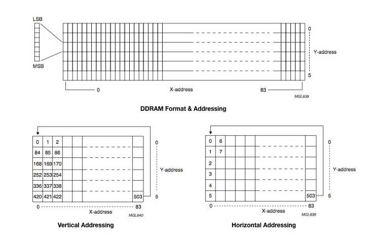
Data can be written into DDRAM with vertical addressing, i.e. from row 0 to row 47 of the display before continuing to the next columns, or horizontal addressing - from first row column 0 to column 83 before continuing on to the next row. We will use horizontal address in our programming.
PCD8544 automatically advances the x and y addresses to the next position based on the vertical or horizontal addressing setting. This is quite handy, for example, when printing a series of characters (i.e. the cursor position), but sometime we want to specify the position where we want to print the display data. The cursor() function allows user to to specify which line (not pixel row 0-47) from 1 to 6 and character-row (not pixel columns 0-83) from 1 to 14 the display data will go.
void cursor(uint8_t row, uint8_t col) {
  if ( (row < 1 | row > LCD_HEIGHT / 8) | (col < 1 | col > LCD_WIDTH / 6)) {
    return;
  }
  _write(CMD, 0x40 | ( row -1 ) );
  _write(CMD, 0x80 | ( col -1) * 6 );
}
Character fonts and display data
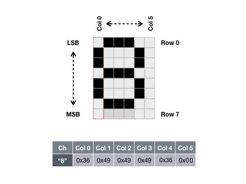
After setting display mode and x-y addressing it is ready to send the data. Each data is indexed to a corresponding array where the dot matrix representation of the character can be accessed. Each character font matrix could be represented by 6-byte of data with each byte arranged vertically with the LSB on top, and the MSB at the bottom, each byte represented the dot matrix of the 6 columns. Since the 8th row and 6th column are always empty (zero) to provide the separation between each font, so each character font can always represented by 7x5 bits of data as shown in the FONT_TABLE array below.
const char FONT_TABLE [][5] = {
    { 0x00, 0x00, 0x00, 0x00, 0x00 }, // 0x20, space
    { 0x00, 0x00, 0x5f, 0x00, 0x00 }, // 0x21, !
    { 0x00, 0x07, 0x00, 0x07, 0x00 }, // 0x22, "
    { 0x14, 0x7f, 0x14, 0x7f, 0x14 }, // 0x23, #
    { 0x24, 0x2a, 0x7f, 0x2a, 0x12 }, // 0x24, $
    { 0x23, 0x12, 0x08, 0x64, 0x62 }, // 0x25, %
    { 0x36, 0x49, 0x55, 0x22, 0x50 }, // 0x26, &
    { 0x00, 0x05, 0x03, 0x00, 0x00 }, // 0x27, '
    { 0x00, 0x1c, 0x22, 0x41, 0x00 }, // 0x28, (
    { 0x00, 0x41, 0x22, 0x1c, 0x00 }, // 0x29, )
    { 0x14, 0x08, 0x3E, 0x08, 0x14 }, // 0x2a, *
    { 0x08, 0x08, 0x3E, 0x08, 0x08 }, // 0x2b, +
    { 0x00, 0x50, 0x30, 0x00, 0x00 }, // 0x2c, ,
    { 0x08, 0x08, 0x08, 0x08, 0x08 }, // 0x2d, -
    { 0x00, 0x60, 0x60, 0x00, 0x00 }, // 0x2e, .
    { 0x20, 0x10, 0x08, 0x04, 0x02 }, // 0x2f, /
    { 0x3E, 0x51, 0x49, 0x45, 0x3E }, // 0x30, 0
    { 0x00, 0x42, 0x7F, 0x40, 0x00 }, // 0x31, 1
    { 0x42, 0x61, 0x51, 0x49, 0x46 }, // 0x32, 2
    { 0x21, 0x41, 0x45, 0x4B, 0x31 }, // 0x33, 3
    { 0x18, 0x14, 0x12, 0x7F, 0x10 }, // 0x34, 4
    { 0x27, 0x45, 0x45, 0x45, 0x39 }, // 0x35, 5
    { 0x3C, 0x4A, 0x49, 0x49, 0x30 }, // 0x36, 6
    { 0x01, 0x71, 0x09, 0x05, 0x03 }, // 0x37, 7
    { 0x36, 0x49, 0x49, 0x49, 0x36 }, // 0x38, 8
    { 0x06, 0x49, 0x49, 0x29, 0x1E }, // 0x39, 9
    { 0x00, 0x36, 0x36, 0x00, 0x00 }, // 0x3a, :
    { 0x00, 0x56, 0x36, 0x00, 0x00 }, // 0x3b, ;
    { 0x08, 0x14, 0x22, 0x41, 0x00 }, // 0x3c, <
    { 0x14, 0x14, 0x14, 0x14, 0x14 }, // 0x3d, =
    { 0x00, 0x41, 0x22, 0x14, 0x08 }, // 0x3e, >
    { 0x02, 0x01, 0x51, 0x09, 0x06 }, // 0x3f, ?
    { 0x32, 0x49, 0x59, 0x51, 0x3E }, // 0x40, @
    { 0x7E, 0x11, 0x11, 0x11, 0x7E }, // 0x41, A
    { 0x7F, 0x49, 0x49, 0x49, 0x36 }, // 0x42, B
    { 0x3E, 0x41, 0x41, 0x41, 0x22 }, // 0x43, C
    { 0x7F, 0x41, 0x41, 0x22, 0x1C }, // 0x44, D
    { 0x7F, 0x49, 0x49, 0x49, 0x41 }, // 0x45, E
    { 0x7F, 0x09, 0x09, 0x09, 0x01 }, // 0x46, F
    { 0x3E, 0x41, 0x49, 0x49, 0x7A }, // 0x47, G
    { 0x7F, 0x08, 0x08, 0x08, 0x7F }, // 0x48, H
    { 0x00, 0x41, 0x7F, 0x41, 0x00 }, // 0x49, I
    { 0x20, 0x40, 0x41, 0x3F, 0x01 }, // 0x4a, J
    { 0x7F, 0x08, 0x14, 0x22, 0x41 }, // 0x4b, K
    { 0x7F, 0x40, 0x40, 0x40, 0x40 }, // 0x4c, L
    { 0x7F, 0x02, 0x0C, 0x02, 0x7F }, // 0x4d, M
    { 0x7F, 0x04, 0x08, 0x10, 0x7F }, // 0x4e, N
    { 0x3E, 0x41, 0x41, 0x41, 0x3E }, // 0x4f, O
    { 0x7F, 0x09, 0x09, 0x09, 0x06 }, // 0x50, P
    { 0x3E, 0x41, 0x51, 0x21, 0x5E }, // 0x51, Q
    { 0x7F, 0x09, 0x19, 0x29, 0x46 }, // 0x52, R
    { 0x46, 0x49, 0x49, 0x49, 0x31 }, // 0x53, S
    { 0x01, 0x01, 0x7F, 0x01, 0x01 }, // 0x54, T
    { 0x3F, 0x40, 0x40, 0x40, 0x3F }, // 0x55, U
    { 0x1F, 0x20, 0x40, 0x20, 0x1F }, // 0x56, V
    { 0x3F, 0x40, 0x38, 0x40, 0x3F }, // 0x57, W
    { 0x63, 0x14, 0x08, 0x14, 0x63 }, // 0x58, X
    { 0x07, 0x08, 0x70, 0x08, 0x07 }, // 0x59, Y
    { 0x61, 0x51, 0x49, 0x45, 0x43 }, // 0x5a, Z
    { 0x00, 0x7F, 0x41, 0x41, 0x00 }, // 0x5b, [
    { 0x55, 0x2A, 0x55, 0x2A, 0x55 }, // 0x5c, back slash
    { 0x00, 0x41, 0x41, 0x7F, 0x00 }, // 0x5d, ]
    { 0x04, 0x02, 0x01, 0x02, 0x04 }, // 0x5e, ^
    { 0x40, 0x40, 0x40, 0x40, 0x40 }, // 0x5f, _
    { 0x00, 0x01, 0x02, 0x04, 0x00 }, // 0x60, `
    { 0x20, 0x54, 0x54, 0x54, 0x78 }, // 0x61, a
    { 0x7F, 0x48, 0x44, 0x44, 0x38 }, // 0x62, b
    { 0x38, 0x44, 0x44, 0x44, 0x20 }, // 0x63, c
    { 0x38, 0x44, 0x44, 0x48, 0x7F }, // 0x64, d
    { 0x38, 0x54, 0x54, 0x54, 0x18 }, // 0x65, e
    { 0x08, 0x7E, 0x09, 0x01, 0x02 }, // 0x66, f
    { 0x0C, 0x52, 0x52, 0x52, 0x3E }, // 0x67, g
    { 0x7F, 0x08, 0x04, 0x04, 0x78 }, // 0x68, h
    { 0x00, 0x44, 0x7D, 0x40, 0x00 }, // 0x69, i
    { 0x20, 0x40, 0x44, 0x3D, 0x00 }, // 0x6a, j
    { 0x7F, 0x10, 0x28, 0x44, 0x00 }, // 0x6b, k
    { 0x00, 0x41, 0x7F, 0x40, 0x00 }, // 0x6c, l
    { 0x7C, 0x04, 0x18, 0x04, 0x78 }, // 0x6d, m
    { 0x7C, 0x08, 0x04, 0x04, 0x78 }, // 0x6e, n
    { 0x38, 0x44, 0x44, 0x44, 0x38 }, // 0x6f, o
    { 0x7C, 0x14, 0x14, 0x14, 0x08 }, // 0x70, p
    { 0x08, 0x14, 0x14, 0x18, 0x7C }, // 0x71, q
    { 0x7C, 0x08, 0x04, 0x04, 0x08 }, // 0x72, r
    { 0x48, 0x54, 0x54, 0x54, 0x20 }, // 0x73, s
    { 0x04, 0x3F, 0x44, 0x40, 0x20 }, // 0x74, t
    { 0x3C, 0x40, 0x40, 0x20, 0x7C }, // 0x75, u
    { 0x1C, 0x20, 0x40, 0x20, 0x1C }, // 0x76, v
    { 0x3C, 0x40, 0x30, 0x40, 0x3C }, // 0x77, w
    { 0x44, 0x28, 0x10, 0x28, 0x44 }, // 0x78, x
    { 0x0C, 0x50, 0x50, 0x50, 0x3C }, // 0x79, y
    { 0x44, 0x64, 0x54, 0x4C, 0x44 }, // 0x7a, z
    { 0x00, 0x08, 0x36, 0x41, 0x00 }, // 0x7b, {
    { 0x00, 0x00, 0x7f, 0x00, 0x00 }, // 0x7c, |
    { 0x00, 0x41, 0x36, 0x08, 0x00 }, // 0x7d, }
    { 0x10, 0x08, 0x08, 0x10, 0x08 }, // 0x7e, ~
    { 0x78, 0x46, 0x41, 0x46, 0x78 }  // 0x7f, DEL
};

void printStr(const char *str) {

  int p = 0;
  while (str[p]!='\0') {
    if ( (str[p] >= 0x20) & (str[p] <= 0x7f) ) {
      for (int i = 0; i < 5; i++) {
        _write(DATA, FONT_TABLE[str[p] - 32][i]);
      }
      _write(DATA, 0x00);
    }
    p++;
  }
}
Display image
The entire display can be used to display a bitmap-like image, it is quite straightforward to display the image once you understand what described in the "Addressing LCD matrix" section above.
void printImage(const char *image) {
  cursor(1,1);
  for (int i = 0; i < (LCD_WIDTH * LCD_HEIGHT / 8); i++) {
    write(DATA, image[i]);
  }
}
Online tutorials often pointed to use Microsoft Paint to create the monochrome bitmap, and then uses a Windows application called LCD Assistant to generate the data array. But I'm a Mac user so LCD Assistant doesn't work for me, and I really prefer a online web service for such application than downloading and install a software. So I created my own Nokia5110 LCD Image Creator web application, it doesn't convert a bitmap image to a data array, but it provide a pixel canvas for you to draw the image and generate the data array to be used for LCD 5110.
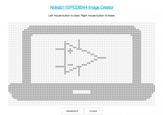
Here is the data array generated by the Nokia5110 LCD image creator for the e-Tinkers logo.
const char eTinkersLogo[504] = {
  0x00, 0x00, 0x00, 0x00, 0x00, 0x00, 0x00, 0x00, 0xe0, 0xf0, 0xf0, 0xf8, 0xfc, 0xfc, 0x7c, 0x7c, 0x7c, 0x7c, 0x7c, 0x7c, 0x7c, 0x7c, 0x7c, 0x7c, 0x7c, 0x7c, 0x7c, 0x7c, 0x7c, 0x7c, 0x7c, 0x7c, 0x7c, 0x7c, 0x7c, 0x7c, 0x7c, 0x7c, 0x7c, 0x7c, 0x7c, 0x7c, 0x7c, 0x7c, 0x7c, 0x7c, 0x7c, 0x7c, 0x7c, 0x7c, 0x7c, 0x7c, 0x7c, 0x7c, 0x7c, 0x7c, 0x7c, 0x7c, 0x7c, 0x7c, 0x7c, 0x7c, 0x7c, 0x7c, 0x7c, 0x7c, 0x7c, 0x7c, 0x7c, 0x7c, 0xfc, 0xfc, 0xf8, 0xf0, 0xf0, 0xe0, 0x00, 0x00, 0x00, 0x00, 0x00, 0x00, 0x00, 0x00,
  0x00, 0x00, 0x00, 0x00, 0x00, 0x00, 0x00, 0x00, 0xff, 0xff, 0xff, 0xff, 0xff, 0x00, 0x00, 0x00, 0x00, 0x00, 0x00, 0x00, 0x00, 0x00, 0x00, 0x00, 0x00, 0x00, 0x00, 0x80, 0x80, 0x80, 0x80, 0x80, 0xf8, 0x10, 0x10, 0xa0, 0x20, 0x40, 0x40, 0x80, 0xfc, 0x80, 0x00, 0x00, 0x00, 0x00, 0x00, 0x00, 0x00, 0x00, 0x00, 0x00, 0x00, 0x00, 0x00, 0x00, 0x00, 0x00, 0x00, 0x00, 0x00, 0x00, 0x00, 0x00, 0x00, 0x00, 0x00, 0x00, 0x00, 0x00, 0x00, 0xff, 0xff, 0xff, 0xff, 0xff, 0x00, 0x00, 0x00, 0x00, 0x00, 0x00, 0x00, 0x00,
  0x00, 0x00, 0x00, 0x00, 0x00, 0x00, 0x00, 0x00, 0xff, 0xff, 0xff, 0xff, 0xff, 0x00, 0x00, 0x00, 0x00, 0x00, 0x00, 0x00, 0x00, 0x00, 0x00, 0x00, 0x00, 0x00, 0x00, 0x00, 0x00, 0x00, 0x00, 0x00, 0xff, 0x00, 0x01, 0x03, 0x01, 0x00, 0x00, 0x00, 0x00, 0x00, 0x01, 0x01, 0x01, 0x82, 0x82, 0x44, 0x44, 0x28, 0x28, 0x10, 0x10, 0x10, 0x10, 0x10, 0x00, 0x00, 0x00, 0x00, 0x00, 0x00, 0x00, 0x00, 0x00, 0x00, 0x00, 0x00, 0x00, 0x00, 0x00, 0xff, 0xff, 0xff, 0xff, 0xff, 0x00, 0x00, 0x00, 0x00, 0x00, 0x00, 0x00, 0x00,
  0x00, 0x00, 0x00, 0x00, 0x00, 0x00, 0x00, 0x00, 0xff, 0xff, 0xff, 0xff, 0xff, 0x00, 0x00, 0x00, 0x00, 0x00, 0x00, 0x00, 0x00, 0x00, 0x00, 0x00, 0x00, 0x00, 0x00, 0x02, 0x02, 0x02, 0x02, 0x02, 0x3f, 0x10, 0x11, 0x09, 0x09, 0x04, 0x04, 0x02, 0x7e, 0x02, 0x01, 0x01, 0x01, 0x00, 0x00, 0x00, 0x00, 0x00, 0x00, 0x00, 0x00, 0x00, 0x00, 0x00, 0x00, 0x00, 0x00, 0x00, 0x00, 0x00, 0x00, 0x00, 0x00, 0x00, 0x00, 0x00, 0x00, 0x00, 0x00, 0xff, 0xff, 0xff, 0xff, 0xff, 0x00, 0x00, 0x00, 0x00, 0x00, 0x00, 0x00, 0x00,
  0xf0, 0xf8, 0xf8, 0xf8, 0xf8, 0xf8, 0xf8, 0xf8, 0xff, 0xff, 0xff, 0xff, 0xff, 0xf8, 0xf8, 0xf8, 0xf8, 0xf8, 0xf8, 0xf8, 0xf8, 0xf8, 0xf8, 0xf8, 0xf8, 0xf8, 0xf8, 0xf8, 0xf8, 0xf8, 0xf8, 0xf8, 0xf8, 0xf8, 0xf8, 0xf8, 0xf8, 0x78, 0x78, 0x78, 0x78, 0x78, 0x78, 0x78, 0x78, 0x78, 0x78, 0xf8, 0xf8, 0xf8, 0xf8, 0xf8, 0xf8, 0xf8, 0xf8, 0xf8, 0xf8, 0xf8, 0xf8, 0xf8, 0xf8, 0xf8, 0xf8, 0xf8, 0xf8, 0xf8, 0xf8, 0xf8, 0xf8, 0xf8, 0xf8, 0xff, 0xff, 0xff, 0xff, 0xff, 0xf8, 0xf8, 0xf8, 0xf8, 0xf8, 0xf8, 0xf8, 0xf0,
  0x00, 0x01, 0x07, 0x0f, 0x0f, 0x1f, 0x1f, 0x1f, 0x1f, 0x1f, 0x1f, 0x1f, 0x1f, 0x1f, 0x1f, 0x1f, 0x1f, 0x1f, 0x1f, 0x1f, 0x1f, 0x1f, 0x1f, 0x1f, 0x1f, 0x1f, 0x1f, 0x1f, 0x1f, 0x1f, 0x1f, 0x1f, 0x1f, 0x1f, 0x1f, 0x1f, 0x1f, 0x1e, 0x1e, 0x1e, 0x1e, 0x1e, 0x1e, 0x1e, 0x1e, 0x1e, 0x1e, 0x1f, 0x1f, 0x1f, 0x1f, 0x1f, 0x1f, 0x1f, 0x1f, 0x1f, 0x1f, 0x1f, 0x1f, 0x1f, 0x1f, 0x1f, 0x1f, 0x1f, 0x1f, 0x1f, 0x1f, 0x1f, 0x1f, 0x1f, 0x1f, 0x1f, 0x1f, 0x1f, 0x1f, 0x1f, 0x1f, 0x1f, 0x1f, 0x0f, 0x0f, 0x07, 0x01, 0x00
};
LCD 5110 backlight control
LED backlight is not part of the functionality of PCD8544 controller chip, but provided by the circuitry of the LCD module itself. It can be connected to the 3.3v/5v power supply with "alway-on" backlight, or to be controlled by one of Arduino Digital pin to turn it on/off via programming. A 330 ohm resistor is used to restrict the current consumption of the LED. A helper function backlight(ON|OFF) can be called to turn ON or OFF the backlight.
void backlight(const uint8_t state) {
  digitalWrite(BACKLIGHT, state);
}
Test it out
By now I have explained how the LCD 5110 actually works in detail and how to use SPI library along with all the Arduino functions that for handling the operation of the LCD module. It is time to test it out. The loop() simply prints 3 lines of string (with both normal and inverse mode) and an e-Tinkers logo image at 5-second intervals each.
void loop()
{
  cursor(2, 2);
  printStr("Hello World!!");
  cursor(4, 2);
  printStr("e-tinkers.com");
  inverse(ON);
  cursor(6,1);
  printStr("** Nov 2017 **");
  inverse(OFF);
  delay(5000);

  backlight(ON);
  printImage(eTinkersLogo);
  delay(5000);
  backlight(OFF);
  clear();
}
Next Step
We've successfully build our own LCD driver, and by doing so, we learn how to get information out from data sheet and gain better understanding on how to use the SPI library to write our own SPI code. We've done a lot. We will soon convert the sketch into an Arduino Library so that other people can download and use it as a library. Stay tune!
Source Code
If you have difficulty in putting the codes together, a complete sketch is available here for download.
The purpose of the sketch is to teach on how to read data sheet and the use of SPI communication to work with the hardware (i.e. in this case LCD5110 module), the code is not optimised with performance and memory usage considerations. If you intend to use the code in your program, it is better to download the LCD-5110-library from my github and install it as an Arduino Library as it has further enhancement and optimisation that is not covered in this article.
This is really great!
Thank you.