I like the low price of ESP-01, but I don't quite like to use it in my project because its design always make me feel like that I'm dealing with an unfinished product. Over the past a couple of months, out of necessity for one of my project, I was forced to spent some time to figure out a better way to use ESP-01 as a WiFi shield.
There are generally two different ways of using ESP-01:
- Use it as a WiFi shield;
- Use it as a stand-alone MCU like an Arduino.
When using it as a WiFi shield, you communicate with it using AT-command, and by default the ESP-01 shipped with At-command firmware.
When you using an ESP8266 as an Arduino, you flash the ESP-01 with Arduino sketch, which overrides the AT-Command firmware and upload it with Arduino core firmware, and allow the ESP-01 to be like a stand-alone Arduino.
Use ESP-01 as a WiFi shield
By default ESP-01 shipped with the firmware that accept AT-Command via a low-speed serial interface, this is quite different from other WiFi SoC's approach, such as uBlox or TI SoC, where SPI is used for interfacing between the host and the WiFi module, allow tighter integration with the host. Although SPI is a serial interface itself, however, it allows very high speed data exchange simultaneously. Even the nRF24L01 module (from Nordic Semiconductor) which has the same form factor and number of pinouts as ESP-01 utilised SPI interface.
I started my project by trying to communicate with ESP-01 using AT Commands with an STM32 Blue Pill as my host. It is painful dealing with AT Command set because it was designed for human-computer interface in the early 80', where user type in various AT commands on the terminal console, the computer echos a human readable string on the screen, the return data from your AT commands are not well structured and has various length, sometime you received "Send Ok", sometime it is just "Ok", if you asked for IP address, it comes back with a string like "+CIPAP_DEF: 192.168.0.100", as the results, the host has to write a lot of codes to parse different message structures for various situations. To extend the AT Commands for handling today's internet protocols such as TCP, UDP, HTTP and even SSL is just seems to be far stretching. This problem can be solved with a well-written library, however, Ai-Thinker is a hardware company, it probably expecting that Espressif - the maker of ESP8266EX will take care the software. Espressif only provide the AT-command firmware and documentation, and leaves the users to develop the library to handle the parsing of AT-command acknowledgements.
Since writing the parser for various AT commands acknowledgements is tedious, over the past several years, many have tried. The most popular library for ESP-01 AT-command is WiFiEsp, it is however has not been actively maintained since around 3 years ago, and the developer mentioned that he no longer have time to maintain the library. Another library WiFiEspAT requires you to upgrade the ESP-01 firmware to v1.7, and as far as I can tell, all the ESP-01 that you could purchased from Aliexpress or most of the Chinese e-commerce vendor today in 2020 are still shipped with AT Command Firmware v1.1 that was released 4 years ago, you will for sure need to first upgrade the firmware before you could using the library, so it is not for users who are new to ESP-01.
AT version:1.1.0.0(May 11 2016 18:09:56)
SDK version:1.5.4(baaeaebb)
compile time:May 20 2016 15:08:19
Half way through of writing my own library, I encountered a library that is well-written with a lot of code comments and quite stable to use. It is however only support HTTP web client, and does not support web server functionality, but this works for me as in most of the IoT applications, you get the data from sensors and send it through a web client to a gateway. So I forked the library and modified it to make it works for STM32 Blue Pill, along the way, I also discovered a bug in parsing the http response packet, so I fixed and host my version of the library LiteESP8266Client at my github. I also wrote another web client example code of using library with a public-accessible web server so it is easier to test during the development without need to worry about setup a server first. To make the code easy to test for my github users, I replaced the actual sensor access with a hard-coded data to simulated the sensor data for the POST request.
This works well if I only send the request to a web server that does not require SSL. But where else nowadays that a web server still using plain HTTP? My project requires the data to be sent to a web server with HTTPS access. This make me to drop what I have done and switch to use the ESP-01 as an Arduino.
Update 27 Jul, 2021 - Recently on replying to one of reader's comment, I spent time dig through the ESP8266 AT Command Set, and realised that an SSL connection can be established by using the TCP connection command
AT+CIPSTART="SSL","url",443. Refer to ESP8266 SSL User Guide for more details.
Use ESP-01 as an Arduino
Using ESP-01 as an Arduino is as easy as using any other Arduino boards. ESP8266 Core for Arduino provides probably the best documentation among all the Arduino boards, with rich libraries and examples for IoT application development. I use the example code HTTPSRequest.ino that came with ESP8266 libraries with slight modification to suit my requirements, and it works well.
Differences between ESP-01 and ESP-01S
Before flashing the ESP-01 with Arduino Code, one need to be aware of the two versions of ESP-01 modules.
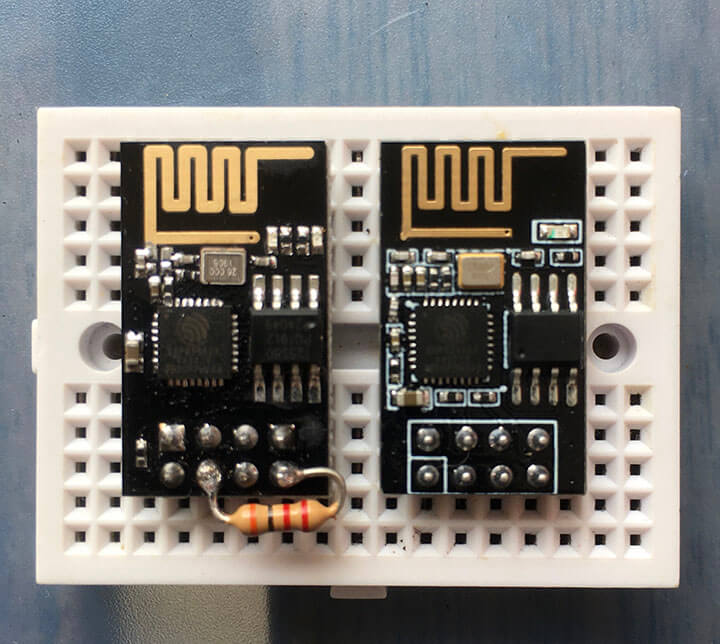
The one on the left is ESP-01 and the one on the right is ESP-01S. Visually, ESP-01 has two LEDs near the PCB antenna, a Blue LED connects to Tx line (GPIO1) and a Red LED as a power indicator. ESP-01S however only has one Blue LED and it is connected to GPIO2 instead. The ESP-01S also added two extra pull-up resistors that you can see between the ESP8266EX chip and the header pins. One of the pull-up resistor is connected between CH_PD and 3v3(VCC) pins.
In the early version of ESP-01, the module often comes with 4Mbit (512KB) SPI memory chip (flash memory), however the ESP-01 that I have comes with 8Mbit (1MB) flash memory. The ESP-01S always equipped with 8Mbit (1MB) flash memory.
My experiences in buying ESP-01 online told me that never trust the images you saw on the e-commerce websites from those Chinese sellers, they almost never publish the SPI memory chip capacity information. The image they shown could be an ESP-01 but you are getting an ESP-01S instead or vice versa.
Upload Arduino sketch to ESP-01
To upload the Arduino sketch to ESP-01 requires a little bit of works on wiring. First, for ESP-01 where it does not have the built-in pull-up resistor on CH_PD pin, you will need to either add a pull-up resistor between CH_PD and 3v3, or connect it directly to 3v3, I personally prefer to solder a 3k-ohm resistor to the pin as you see in the picture so that I don't need to worry about whether I'm dealing with an ESP-01 or ESP-01S.
It will be easier to put ESP-01 into programming mode by adding two push button switches between ground and GPIO0 (Flash button) and RST (Reset button) pins respectively. The two buttons however do not required for normal operation of ESP-01.
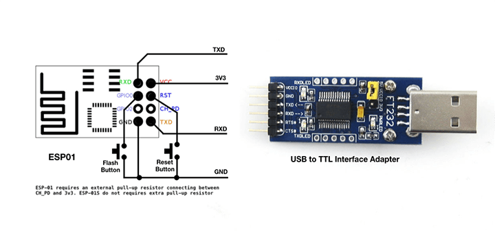
To put ESP-01 into programming mode:
1) Press and hold BOTH buttons;
2) Release the Reset button while keep holding the Flash button until the upload is completed;
3) Press Reset to start the newly uploaded program.
Although I'm able to connect to a web server with SSL, I won't want to use ESP-01 (or a full version of ESP8266-based Arduino board) solely as my MCU, 1) ESP-01 itself has limited number of GPIO pins that meet my project requirements; 2) Even with other ESP-8266-based boards has only one ADC with 10-bit resolution, it is noisy and not linear (ESP32 is not better although it has 12-bit ADCs), which is exactly the reason that I chose STM32 for my project.
A better way to use ESP-01 as an WiFi Shield
This lead me to create a better way to use the ESP-01 as a WiFi shield, where ESP-01 will be responsible for establishing WiFi and and HTTP(S) connection as you see in "Using the ESP-01 as an Arduino". A Host (STM32 Blue Pill in my case) will be used as a sensor node, the Host communicate with ESP-01 via a serial interface, in a way, this is similar to use the ESP-01 with AT command firmware, except the firmware on the ESP-01 is replaced with the Arduino web client, and we can design our own communication requests and responses between the serials.
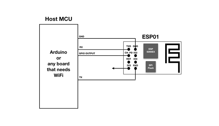
Serial interface state machine
In order to make the exchange of information between the Host and ESP-01 easier to decode and more structural, I borrow the concept of state machines from Nick Gammon on State Machines and make a simplified version of serial state machine on both the Host and ESP-01.
On the Host, it acts as a Serial Controller waiting for the state of "Wifi Ready" from the ESP-01, and only when the ESP-01 is ready, the Host will gather the sensor info and send the data as a serialised JSON object to the ESP-01. Another state that the Host is monitoring is whether the ESP-01 has done all the work and ready to go into sleep mode (ESP-01 sent back "Going Sleep"), this allows the Host to go into deep sleep itself (or with a simple long delay) before the next round of sensor data acquisition. To wake up ESP8266, GPIO16 pin of ESP-01 should be used and connect to RST pin of ESP-01 to wake-up the chip, ESP-01 however does not expose the GPIO16 on its connection header, so I connect a GPIO pin from the Host to CH_PD pin of ESP-01 and generates a short pulse to wake-up (technically reset) the ESP-01.
The code below is based on Arduino Nano (I test it on both an Arduino Nano and STM32 Blue Pill) through a SoftwareSerial interface, and D5 is used to wake-up the ESP-01. The code can be easily modified for using with STM32 where HardwareSerial port will be used instead of SoftwareSerial.
// Host Serial Controller
// This sketch send sensor data in serialized JSON to an ESP01 web client via serial port

#include <Arduino.h>
#include <SoftwareSerial.h>
#define MAX_LEN 50
#define ESP_RESET 5    // D5 connect to ESP01 CHIP_EN (CH_PD) pin
#define SENSING_INTERVAL 600000

char incomingMsg[MAX_LEN];
uint8_t count = 0;

SoftwareSerial espSerial(2, 3);  // rx, tx

void processData() {
  Serial.println(incomingMsg);
  if (strcmp(incomingMsg, "Wifi Ready") == 0) {
    char data[55] = "{\"temp\":28.3, \"ph\":5.8, \"ec\":1.8, \"battery\":3.3}\n";
    espSerial.print(data);
    return;
  }
  if (strcmp(incomingMsg, "Going Sleep") == 0) {
    delay(SENSING_INTERVAL);
    digitalWrite(ESP_RESET, LOW);    // send a pulse to wake up ESP01
    delay(10);
    digitalWrite(ESP_RESET, HIGH);
  }
}

void setup() {
  Serial.begin(74880);
  espSerial.begin(74880);
  pinMode(ESP_RESET, OUTPUT);
  digitalWrite(ESP_RESET, HIGH);
}

void loop() {
  while (espSerial.available() > 0) {
    char c = espSerial.read();
    switch (c) {
      case '\r':
        break;
      case '\n':
        incomingMsg[count] = '\0';
        processData();
        count = 0;
        break;
      default:
        if (count < (MAX_LEN - 1)) {
          incomingMsg[count++] = c;
        }
        break;
    }
  }
}
On the ESP-01, a very similar state machine is used to detect the receive of '\n' that signifies the end of a data string, and send out the received string as HTTP POST payload to the server. As the establish of WiFi connection could take as long as 5 seconds for the initial setup and shorter for the subsequent reconnection, the ESP-01 will send a string of "WiFi Ready" state to the Host upon the establish of WiFi connection, and the Host will only send out sensor data upon receiving of this state. Once the HTTP post request is sent, the ESP-01 also sent back the HTTP response status code (such as 200 or 404) as a string to the Host. When everything is done and prior going to deep sleep, ESP-01 will send out another status "Going Sleep" to the Host.
// Serial WebClient for ESP01
// This sketch get JSON data via serial port from host controller and send
// https POST request to a web server

#include <Arduino.h>
#include <ESP8266WiFi.h>
#include <ESP8266HTTPClient.h>
#include <WiFiClientSecureBearSSL.h>
#define MAX_LEN 55    // make sure it is sufficient for your data

char incomingMsg[MAX_LEN];
uint8_t count = 0;

// configure those parameters for your network
const char *ssid = "your-wifi-ssid";
const char *password = "your-wifi-password";
const char *url = "https://httpbin.org/post";
const uint8_t fingerprint[20] = {0xBF, 0x5C, 0x1E, 0x24, 0xA1, 0xB7, 0x73, 0xCF, 0xE6, 0xBF, 0xBC, 0xF5, 0x8A, 0x58, 0xF3, 0xC2, 0xE4, 0xB6, 0x98, 0xE1};
void sendPostRequest() {
  std::unique_ptr<BearSSL::WiFiClientSecure>client(new BearSSL::WiFiClientSecure);
  client->setFingerprint(fingerprint);

  // send https POST request to server
  HTTPClient https;
  https.begin(*client, url);
  https.addHeader("Content-Type", "application/json");
  int statusCode = https.POST(incomingMsg);

  // send server response http status code through serial
  char statusAscii[5];
  itoa(statusCode, statusAscii, 10);
  Serial.print(statusAscii);
  Serial.print('\n');

  https.end();
}

void setup(void) {
  Serial.begin(74880);
  WiFi.begin(ssid, password);
  while (WiFi.status() != WL_CONNECTED) {
    delay(100);
  }
  Serial.print("Wifi Ready\n");
}

void loop(void) {
  while (Serial.available() > 0) {
    char c = Serial.read();
    if (c == '\n') {
      incomingMsg[count] = '\0';         // terminating null byte
      sendPostRequest();
      count = 0;                      // reset buffer pointer
      Serial.print("Going Sleep\n");
      delay(50);                      // for Serial to finish sending
      ESP.deepSleep(0);
    }
    else {
      if (count < (MAX_LEN - 1)) {
        incomingMsg[count++] = c;
      }
    }
  }
}
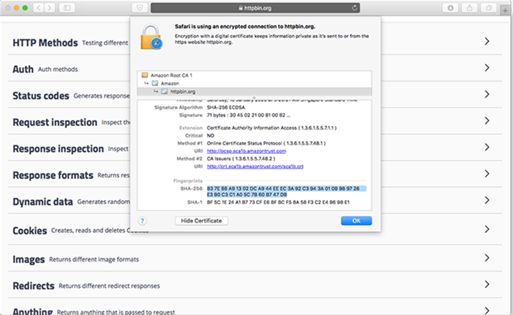
To get the SHA fingerprint of web server, open your browser with web server's url, click on the little lock icon in front of the url, click on "Show Certificate", click on "Details" and scroll all the way down, you will see the fingerprints for both SHA-256 (32 bytes) and SHA-01 (20 bytes), we only use the SHA-1 fingerprint. This works for both Safari and Chrome. For Firefox, the exact steps are slightly different.
The ESP-01 requires 3.3V supply as its power source, and most of the Arduino boards such can't supply enough current to meet the ESP-01's need so an external power source would be required. ESP-01 consumed a much as 180mA during short burst of data communication, and the module will consumed an average of 30mA in idle, as I'm powering both STM32 and ESP-01 with a 3.7v battery, it is a good idea to put the ESP-01 in deep sleep mode in between the data acquisition cycling. When the ESP-01 in the deep sleep mode, the entire ESP-01S module consumed less 0.1mA in my measurement (my Multimeter is not able to measure uA consumption, according the data sheet of ESP8266EX, the chip itself will only consumed 26uA during deep sleep).
Conclusion
To implement a serial state machine between Host and ESP-01 provide a better way to use ESP-01 as a WiFi shield, allowing ESP-01 to utilise Arduino library and sketch and focus on WiFi and internet connectivity, while the Host MCU acts as a sensor node with very simple program logic and parsing of incoming states without the need of any third-part library. The state machines are highly customisable and extendable to suit any application needs. Extra benefits including the ability to put both the Host and ESP-01 into deep sleep and wake-up the ESP-01 on demand to reduce power consumption. The only drawback to this approach is that it requires to maintain two codebases for different platforms rather than just one codebase for the Host.
Github
The complete codes for both the Host Serial Controller and ESP-01 Serial Web Client are available on my github.
Hi I came across your nice idea “A better way to use ESP-01 as WiFi shield” since we are building a community project M10CUBE.
We are in the middle in designing the STM32 board but also the sensor board.
you see one M10CUBE application will be a citizen of Volos, Greece air pollution project so the STM32+ESP-01+LoRa and the M10CUBE sensor board will be used in pair.
I would like to have your idea on the design . Is it better to put the ESP-01 on the sensor board? Is ESP-01 good choice after all? And some other various questions that we like you to share with us since you worked on STM32 and ESP-01 .
Thanks in advance
Vasilis
Not quite sure what you mean “put the ESP-01 on the sensor board”, the ESP-01 is always physically attached to the sensor board, it just that from a functional diagram, they are separated as two parts, one as a sensor node(stm32), and another as a wifi-shield(esp-01), each with its own platforms(stm32 versus esp8266) and its own sketch.
This is really depend on what is the purpose of having ESP-01 and what kind of sensors you have.
In my case, I need to have full function wifi-connectivity and web client to post the data to a database in an IoT gateway (a Raspberry Pi), and also because I have several of ESP-01 with me (otherwise I would use an ESP-12F for my project). Another reason I choose this hybrid approach of having a sensor board and an WiFi shield is because I have several ADC sensor inputs, and I can’t simply use an ESP8266 or ESP32 board because those boards’ ADC are non-linear and noisier, so if your sensors are all digital (or have some external ADC with an I2C interface), then you probably could do away with the STM32+ESP01 approach and directly using an ESP8266 board for have both sensors and wireless connectivity.
In the case where you don’t need WiFi function to establish a HTTP connection but just need a wireless connectivity to send short burst of sensor data, then a pair of nRF24F01 or ESP-01 running ESP-Now protocol with a master/slave (controller/receiver) configuration might be a better solution for farer transmission distance and better battery life. I recently has a project where all the sensors are about a 100-200 meters away, each node has only one or two sensors, so I use ESP-01 directly as both the MCU and 2.4GHz wireless interface (i.e. without extra MCU board) and send data to an ESP-01 configure as an ESP-Now Controller which pass the data to the Raspberry Pi via a serial interface, the Raspberry Pi take the data and save it to database or serve it to the web request.
Hope this will help. Let me know or PM me if you have more questions.
I’m a beginner in the word of Arduino and friends. I’ve already succeded with Node MCU ESP 32S Dev board and Aduino Uno.
I recently bought an ESP-01S module, but had no luck. Not having red LED make me hard to tell my ESP-01S is working or not.
I use the common usb to ttl interface (with yellow female header and CH340 chip). I use a button between RST and GRN, also put a jumper between GPIO0 and GRN like you mention above.
No response from my ESP module. My Arduino IDE aways failed to connect. Just like the ESP module does not exist.
No response either from AT command. What i should do? is my ESP-01S faulty?
I need for my project because the small size and wifi capability.
Please help. Thanks.
Based on what you described, you are likely have an faulty ESP-01.
Hi! I would like to sent an input signal from 1-ESP-01 to an Arduino connected with another ESP-01. Do you know how I should do? I didn´t find a way to chosse an IP address and sent a message to it.
Can you please provide more details about how to connect to Firebase, if it’s possible, by running AT commands?
I’m asking if it’s possible since one the one hand, you wrote that “This works well if I only send the request to a web server that does not require SSL”, but on the other hand, you wrote in Stack Overflow that it should be possible.
Reference:
https://stackoverflow.com/questions/65499281/how-to-connect-the-esp8266-wifi-module-to-firebase-through-the-stm32cubeide
It has been a while but I remember one of the issues that I’m facing was to find the AT commands for supporting HTTPS, which I can’t find in the Espressif AT Command documentation. I just checked the latest Espressif AT Command set, it still does not support HTTPS/SSL. I’ve updated my Stack Overflow with clarification.
I recently dig through the ESP8266 AT Command Set and realised that an SSL connection can be established using TCP connection AT command
AT+CIPSTART="SSL","url",443. It does not seem to support SNI and also WiFi passthrough mode is not supported when using SSL.I brought issue 44 of Hackspace magazine published by the Raspberry Pi foundation. ( free pdf )
There were two a useful articles about ESP8266 and using Webpages and Chrome / or Edge to control serial ports.
I have been assemblin this page:- https://homepages.plus.net/dougrice./dev/DigiSpark/simpleterm/simpletermESP01.html
It only runs it off the desktop or an HTTPS server.
It allows the AT commands to be sent using a button.
The serial port API is experimental and needs enabling. It is not bug free.
https://www.anticyclone-systems.co.uk/aslwebterm.html
Thanks for your interesting Blog!
Hey! Thank you for all your work on the library. I am really new to the ESP8266 and have an ESP-01. In order to use your library and Use the ESP-01 as a WiFi shield, how do I wire the esp-01 to the arduino? It probably is a stupid question or maybe you explained it and I missed it. Even just a link to someone using your library with step by step instructions would be super awesome.
Thank you again.