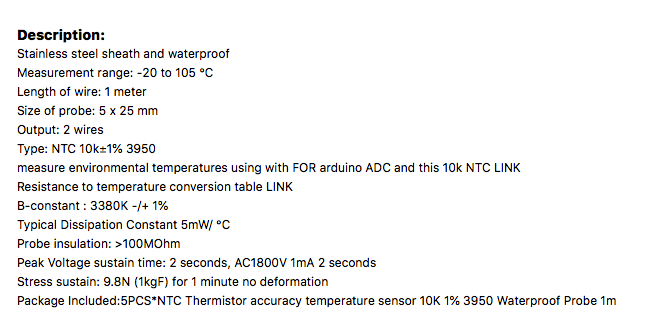
I recently accidentally bought 5 pieces of thermistor, so I tried it out on both of my Arduino and ESP32 modules, and I have surprise findings on both Arduino and enchanted unexpected ESP32's ADC linearity issue.
NTC Thermistor
What I means that I "accidentally" bought 5 pieces of thermistor for SGD5.40 (approximately a little less than USD4.00) is that I thought those were DS18B20 temperature sensor when I placed order and I didn't pay too much attention about it because I know DB18B20 well from my previous projects and there are similar form factor for DS18B20 available in the market. It is not until I received the goods and decided to put it in use that I realised that it has only two pins instead of three pins as DS18B20 is. I quickly look at the product description, silly me, it was all written there that these are NTC thermistor. NTC thermistor is really easy to use, so I decided to apply it to my project.
Negative Temperature Coefficient (NTC) thermistor is the most common type of thermistors, and it is very easy to use. The one that I purchased has a resistance of 10k at temperature of 25 degree Celsius and the resistance go up when temperature go down. So in order to measure the temperature, what you need is a voltage divider circuits consists of a known resistor (R1) connected in serial with the thermistor (Rt), apply a voltage reference (Vs) to one end of the resistor, and connect the other end of the thermistor to ground, the voltage across the thermistor (Vo) is read to determine the temperature based on the voltage reading. As the resistance of the thermistor changes with temperature, the voltage Vo will varies accordingly, this can be easily measured with an Analog In on an Arduino to get the reading.
Vout/Rt = Vs/(R1 + Rt)
Vout = Vs * Rt/(R1 + Rt)

or

Rt = R1 * Vout/(Vs - Vout)
These formulas help us to measure the resistance Rt of the thermistor indirectly by measuring the Vout, as most of the microcontroller such as Arduino provided input for getting the reading of an analog voltage via an ADC (Analog-Digital Converter). But what we really want is the temperature reading, not just a resistance! According to the Steinhart-Hart equation, the resistance of a semiconductor at different temperatures follow an equation that consists of a series of coefficients. These coefficients can be obtained through some calibration processes. Luckily, most of the NTC thermistor manufacturers publish a coefficient called B parameter (which shown on the product description that I purchased as NTC 10k+/-1% 3950, the 3950 is the B parameter) which allows to simply the formula as:
    1/T = 1/To + 1/B * ln(Rt/Ro), so
    T = 1 / (1/To + 1/B * ln(Rt/Ro))
Where:
T is the temperature to be measured in Kelvin;
To is the reference temperature in Kelvin for 25 degree Celsius;
Ro is the thermistor resistance at To;
B is Beta or B parameter, provided by manufacturer in their specification.
Using Thermistor with Arduino
As we have all the formulas that we need for programming the Arduino, we can therefore read the voltage Vout via A0 pin on Arduino.
    // NTC B3950 Thermistor
    // the formula for temp in kelvin is
    //                 1
    // T = ----------------------------
    //     1/To + (1/beta) * ln(Rt/Ro)
    //
    // https://en.wikipedia.org/wiki/Thermistor

    int ThermistorPin;
    double adcMax, Vs;

    double R1 = 10000.0;   // voltage divider resistor value
    double Beta = 3950.0;  // Beta value
    double To = 298.15;    // Temperature in Kelvin for 25 degree Celsius
    double Ro = 10000.0;   // Resistance of Thermistor at 25 degree Celsius

    void setup() {
      Serial.begin(9600);

      ThermistorPin = A0;
      adcMax = 1023.0;   // ADC resolution 10-bit (0-1023)
      Vs = 5.0;          // supply voltage

    }

    void loop() {
      double Vout, Rt = 0;
      double T, Tc, Tf = 0;

      Vout = analogRead(ThermistorPin) * Vs/adcMax;
      Rt = R1 * Vout / (Vs - Vout);
      T = 1/(1/To + log(Rt/Ro)/Beta);  // Temperature in Kelvin
      Tc = T - 273.15;                 // Celsius
      Tf = Tc * 9 / 5 + 32;            // Fahrenheit
      Serial.println(Tc);

      delay(2000);
    }
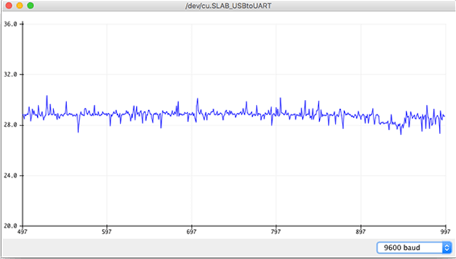
The Arduino program is quite straightforward once you understand the formulas. The Arduino ADC provided a 10-bit resolution, what this means is that giving a voltage input of 5v, the reading will be 1023, and a reading of 512 would be 512 * 5v/1023=2.5v and so on so for. The temperature value derived from the B parameter formula is in Kelvin, but it is easy to convert it to Celsius by subtracting it with 273.15, I add the formula for converting Celsius to Fahrenheit, but only print out the Celsius value to the Serial Console.
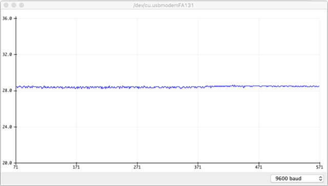
The output of the reading is quite stable as you can see from the screen capture of the Arduino Serial Plotter.
The Unexpected ESP32 ADC Non-Linearity
I'm more often use ESP32 than Arduino for my project nowadays as it has a compact form factor, faster CPU with a lot of more memory, but more importantly for me is the built-in wireless connectivity with WiFi and Bluetooth. Particular for this project, I would need both more than one ADC inputs and wireless connectivity eventually. The ESP32 ADC can also be configured with 9 to 12-bit resolution, for input voltage up to 3.3v. I was expecting 3.3v would be less noisy than 5v as it is further regulated from the supply voltage of 5v from USB, and 3.3v over 4095 ADC steps at 12-bit resolution would provide better precision than Arduino as well. So ESP32 seems to be perfect for my project.
For the programming, I only need to change the settings in the setup(), the rest is the same as Arduino sketch:
    ThermistorPin = 34;
    adcMax = 4095.0; // ADC resolution 12-bit (0-4095)
    Vs = 3.3;        // supply voltage
Pin 34 refered to ESP32 GPIO 34 according the the ESP32 Dev Board Pin Map which can be configured as ADC6.
But when I run the program on ESP32, the reading of the temperature is almost 10% off compare to the reading from Arduino, this translate into about 2.3 - 2.4 degree Celsius differences in my case, where does it come from?
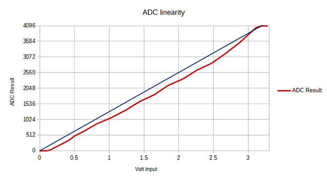
After digging through various websites, I realised that the delta was caused by the non-linearity of ESP32 ADC. There are lengthy discussions on Expressif github and forum about the issue. Basically, ESP32's ADC is non-linear as shown in this chart below:

Although Espressif (ESP32 chip manufacturer) claims that it has fixed the issue by implementing a calibration algorithm during the manufacturing process for chips that are shipped on and after 1st week of 2018, the ESP32 WROOM-32 modules that I bought in Feb 2019 from Shenzhen clearly were produced before that. The fix described on the website seems to be a little troublesome and risky to do and will take me much longer time so I decided to look for alternative to fix the issue.
Fix ESP32 Non-linarity with a Lookup Table
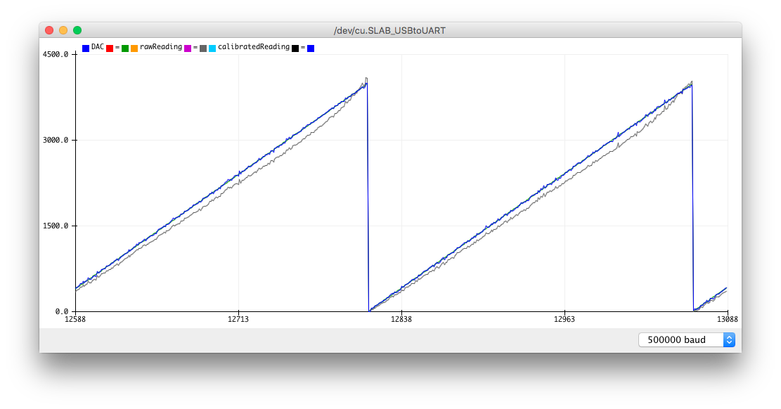
Bury deep in an Expressif Forum discussion, Helmut Weber describes a way to generate a lookup table by feed a Digtial-to-Analog (DAC) output generated by ESP32 into the ADC input to compare the known value of DAT output with ADC reading, and use the lookup table to correct the raw ADC reading. He generates a whole table consists of 4096 values covering the entire 12-bit ADC range, and uses it to get the corrected value. The lookup table values varies from device to device due to the internal reference voltage of each ESP32 varies, so Weber's pre-generated lookup table that he used doesn't work for my device. So I connect the DAC output pin 25 (DAC_CHANNEL_1) to ADC 34 (this is the pin that I'd want to use for my thermistor reading), and run Weber's program to generate the lookup table for my ESP32.
Helmut Weber's original code has a couple of bugs, a clean-up and bug-fixed version for ADC calibration program is hosted on my github.
The ESP32 offers two DAC outputs (on GPIO25 and GPIO26) with 8-bit resolution, but the ADC is 12-bit resolution, so there will be some loss due to interpolation between 8-bit to 12-bit, but it is not significant compare with the noise level of ESP32 (more on that later).
The calibrated result is quite impressive, the plot below shows the raw ADC reading version calibrated reading.
Copy and paste the generated lookup table into my program as the declaration of the lookup table, and change the loop() so that instead of using the the data read from ADC directly, it uses the value get from analogRead(34) as the reference index to get the corrected value from the lookup table.
    const float ADC_LUT[4096] PROGMEM = { 0,
    17.0000,18.4000,19.8000,21.2000,22.8000,24.0000,25.8000,27.0000,28.8000,30.0000,31.6000,32.8000,34.0000,35.2000,36.6000,37.8000,
    . . . . . .
    3990.6001,3991.0000,3991.8000,3992.6001,3993.0000,3993.8000,3994.6001,3995.0000,3995.8000,3996.6001,3997.0000,3997.8000,3998.6001,3999.0000,3999.80
    };

    void loop() {
      double Vout, Rt = 0;
      double T, Tc, Tf = 0;

      double adc = 0;
      if (esp32) {
        adc = analogRead(ThermistorPin);
        adc = ADC_LUT[(int)adc];
      }
      else {
        adc = analogRead(ThermistorPin);
      }
      Vout = adc * Vs/adcMax;
      Rt = R1 * Vout / (Vs - Vout);

      T = 1/(1/To + log(Rt/Ro)/Beta);    // Temperature in Kelvin
      Tc = T - 273.15;                   // Celsius
      Tf = Tc * 9 / 5 + 32;              // Fahrenheit
      if (Tc > 0) Serial.println(Tc);

      delay(2000);
    }
Please noted that instead of paste the long lookup table here, I only show partial of the code here, you can see the complete code from my Github repository.
The noise of ESP32 ADC
Non-linearity is not the only problem of ESP32 ADCs, the reading from ESP32 is also much noisier than the output from Arduino.
The noise is probably due to the higher CPU clock and small form factor of ESP32 module. The noise can be smooth out a little bit with some filtering algorithm or by adding 0.1uF capacitor to both the ADC input and the 3.3v pin close to the thermistor.
Conclusion
Thermistor is easy to use and quite stable with an Arduino, I'm impressed by the Arduino ADC performance despite it only offers 10-bit resolution.
I like ESP32 in general as it offers many good features for IoT projects, such as wireless connectivity and deep sleep, but I'm quite disappointed on the ADC linearity issue and this was something quite unexpected when I start this project. Personally I feel it is more important to offer one good ADC than offer a bunch of mediocre ADCs. The lookup table solution offers a decent solution for correcting the linearity issue, especially if what you are measuring fall within a narrow spectrum, this should be okay for most of hobby projects, but it is still quite troublesome as the calibration need to be carry out on each ESP32 you used. For production projects, I would consider to use a separate ADC integrated circuit rather than using ESP32's ADC.
Hi – I was examining your use of this lookup table. There seem to be some random values in the table that don’t make sense. For example, in line 133 of your source code, there is a value of 4089.8000 in between values of 1825. and 1826: {1824.6000,1825.0000,4089.8000,1826.4000,1827.0000}. Similar anomalies can be found in lines 34, 87, 106, 122, 133, 136, 138, 149, 154, 184, 187, etc.
These values should produce incorrect value spikes when accessed…have you experienced this?
I tried using Helmut Weber’s lookup table generator that you linked to, and I also get these sporadic 4xxx values. I’ve narrowed the issued down to his code where he manipulates the Res2 values, but haven’t been able to understand why this is happening.
Can you explain to me if you are getting glitches in your data as a result of these 4xxx values peppered in the lookup tables?
Thanks…
Good catch. I actually didn’t noticed that. The table that I used was generated by me, so if the same anomalies happened to my table, Weber’s table as well as yours, then I tend to think there is something wrong with algo in handle some corner cases. I’m currently traveling on an overseas assignment so I don’t have an ESP32 with me now, but I would certainly like to find out more. Stay in touch and let me know if you have any new finding.
Thank you. I love you so much.
Very thorough. One question though. You say that the description states 3950 to be the B factor, but if you ask me it clearly states :
B-constant 3380K +/-1%
Am I just misunderstanding?
Yes, you are right for this particular specification shown on the store that 3380 should be used as beta value.
Hi folks
In my project I am only interested in temperatures between 10 C and 30C.
Instead of using a look up table with with so many values, I used only 5 values (times 2) and translate cnts directly to temperature. First I calibrated the system by replacing the thermistor with a fixed resistor (equivalent to 8.5C) and recorded the counts. Repeat this 5 more times with different fixed resistor values. My table looks something like this
int cnt[5] = {1163, 1569, 1657, 1734, 2021};
float temp_point[5] = {8.5, 18.0,  21.0, 23, 30.5};
When using the thermistor, I read the a/d cnts, and calculate a straight line between two points in the above table to get the exact temperature. No B value required.
Here is the function to read the thermistor of my code.
float read_thermistor() { int i, cntx; float temp, m, b; // variables for line equation // look up table to convert counts to temperature int cnt[5] = {1163, 1569, 1657, 1734, 2021}; float temp_point[5] = {8.5, 18.0, 21.0, 23, 30.5}; cntx = analogRead(34); // determine which two point to used based on cntx if (cntx < cnt[1] ) { i = 0; } if(cntx <= cnt[1] ) i = 1; if(cntx <= cnt[2] ) i = 2; if(cntx <= cnt[3] ) i = 3; // Calculate slope and constant for line : temp = mx + b m = (temp_point[i + 1] - temp_point[i] ) / ( cnt[i+1] - cnt[i] ); b = temp_point[i] - ( m * cnt[i] ); temp = m * cntx + b; return(temp); }Thanks for sharing. Great work!
Hi Rob,
Very innovative approach. Thanks for sharing.
I tried doing the full LUT table, and it crashed my code, and this shorten LUT really helps.
1. Can you / Someone here be kind enough to show in detail how Rob managed to get his shorten looked up table?
int cnt[5] = {1163, 1569, 1657, 1734, 2021};
float temp_point[5] = {8.5, 18.0, 21.0, 23, 30.5};
2. Does this mean that every ESP32 device need to be repeated due to non-linearity of its ADC?
3. How can this concept be applied to other analog measurements? Am wondering whether there is a way to avoid using an external ADC.
Thanks in advance.
I was struggling with the ADC on my new ESP32 until I read this article. It helped a lot. The LUT solution seems very good.
However, when I use the LUT that I obtain through the calibration process, it is much better than without but not as close as it should be. It’s still off by about 10% through much of the range. The calibration process relies on the DAC being somewhat accurate. Maybe mine’s not?
I was also puzzling over the algorithm. I keep trying to think through it and it’s not getting through my thick skull. The LUT generation process outputs known voltages using the onboard DAC, representing these as values from 0 to 255 (since the DAC is 8 bits). For each of these values, it then reads the result from the ADC. It then interpolates for the in between values to get 4096.
So far so good, but I’m not sure why the LUT works by indexing with a value I read from the ADC. It seems like I should be doing a reverse look-up instead, but it obviously works in the forward direction. I tried thinking of an example: the LUT generator would take 128, which should be 1/2 of Vcc, outputs that to the DAC, and then the ADC reads back a digital value in the 0-4095 range that should represent that voltage relative to Vcc. If the ADC is perfectly accurate, it should get 2048, or 1/2 of the range 0-4095. Let’s say though it reads back 1995. Now the LUT has, at index 2048 the value of 1995.
Using the LUT, that would mean if I read a value of 2048 from the ADC, I would translate it to 1995 which seems the opposite of what I’d want. It would seem that what I want is, on a reading of 1995, translate that to 2048.
My thinking is obviously twisted around. Looking for some untwisting. 🙂
Hi thanks for sharing,
I use your code to generate the ADC_LUT but the result i read for thermistor is worst with LUT than without.
For Example with NTC 3950 100K and 10k serial resistor:
Room temperature => 25.3°c
NTC without LUT => 23.35°c with ADC read @ 3739
NTC With LUT => 13.5°c with LUT conversion to 3870
Any idea ?
Thanks a lot
Julien
Hello,
My group and I are working on a project for senior design at UFC for engineering. We would like to use your pictures for explanation in our paper. We are using it as a reference and would like to put it in our report, is that ok?
Thanks,
Eric Baez
University of Central Florida
Electrical Engineering BS
Yes, feel free to use it as long as you provided citation in your report.
BTW, I’ve removed your email from your post for your own privacy protection.
Thanks for the info.
Just on the noise you suggest:
“…adding 0.1uF capacitor to both the ADC input and the 3.3v pin close to the thermistor.“
I have seen other people suggesting the capacitor should be between the ADC and ground. The Espressif docs only reference the ADC pin and do not say what it should be connected to.
Does it matter?
Sorry if the sentence is not clear enough. What I means is to add one 0.1uf between the ADC input and ground, and another 0.1uF between the 3.3V and ground near the thermistor. The 0.1uF is for filtering out the high frequency noise from the power line.
I have a question regarding the outputted results of this code. When putting the thermistor next to an ice cube for example, the expected temperature would get increasingly lower, but when running this code, the temperature seems to increase. Is there an error in the formula, or I am misunderstanding the results?
It depends on how you wiring your thermistor and type of thermistor you have.
Hi,
just a confirmation, you actually change the VCC for the thermistor to 3.3v as well when switching over to ESP32 as well, correct? Because in this case, if using 5v supply voltage for the bridge circuit, the analog read value can reach 3.3v at around 38C and the ADC would not be able to read any further.
Thanks.
Dear friend,
Thank you for sharing! Your technique has given me new hope!
By implementing this solution, my output has significantly improved, but I still have some discrepancies: at room temperature (around 20ºC), the output from the ESP32 shows a difference of 3 degrees higher, meaning around 23ºC; as the temperature increases, the difference becomes even greater; at 70ºC, the ESP measured 78ºC!
Any ideas on how I can adjust this?
Thanks a lot!
Use a voltmeter to check if your R1 is really at 10k and adjust the value used in the formula accordingly. Check the data sheet of your thermistor to confirm its beta value match the one used in the formula.