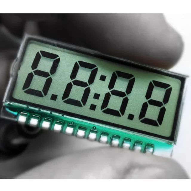
A while back when browsing Aliexpress, I saw this 4-digit segment LCD glass that selling for slightly more than USD1.00, so I bought it out of curiosity and this article describes on how to drive the LCD glass with GPIO, no dedicated LCD controller used.
Segment LCD (a.k.a. LCD glass)
Most of the popular LCD displays, such as LCD 1602, it has a LCD controller bonded and exposy-sealed on the back of LCD display. The controller make the interface with the display much simpler and easy to interface with an MCU.
But for the 4-digit seven-segment LCD glass that I purchased, it is a so-called segment LCD or LCD glass, meaning that other the display glass itself, there is no additional electronics parts attached to it. Microchip PIC product line has many MCUs that have build-in LCD controller as part of the MCU offers, and could be used to drive the segment LCD glass. But I never use PIC microcontrollers before, and has no intension to use it just for this segment LCD, so I'm interested to see how I can "bit-banging" with GPIO pins to control the segment LCD.
The Aliexpress seller's product page provided a a jpeg image which is sort of the "specification" of the display. The "specification" provides two crutial information for understanding how the segment LCD should be driven. First, it shows that the display requires 3.3v with a driving condition of 1/4 duty and 1/3 bias. Secondly, the table at the bottom of the image shows that all the segment A and B are connected together and control by the com1, all the segment F and G are connected together and control by the com2, all segment E and C are with com3, and last all decimal point dots, semi-column and segment D are with com4.
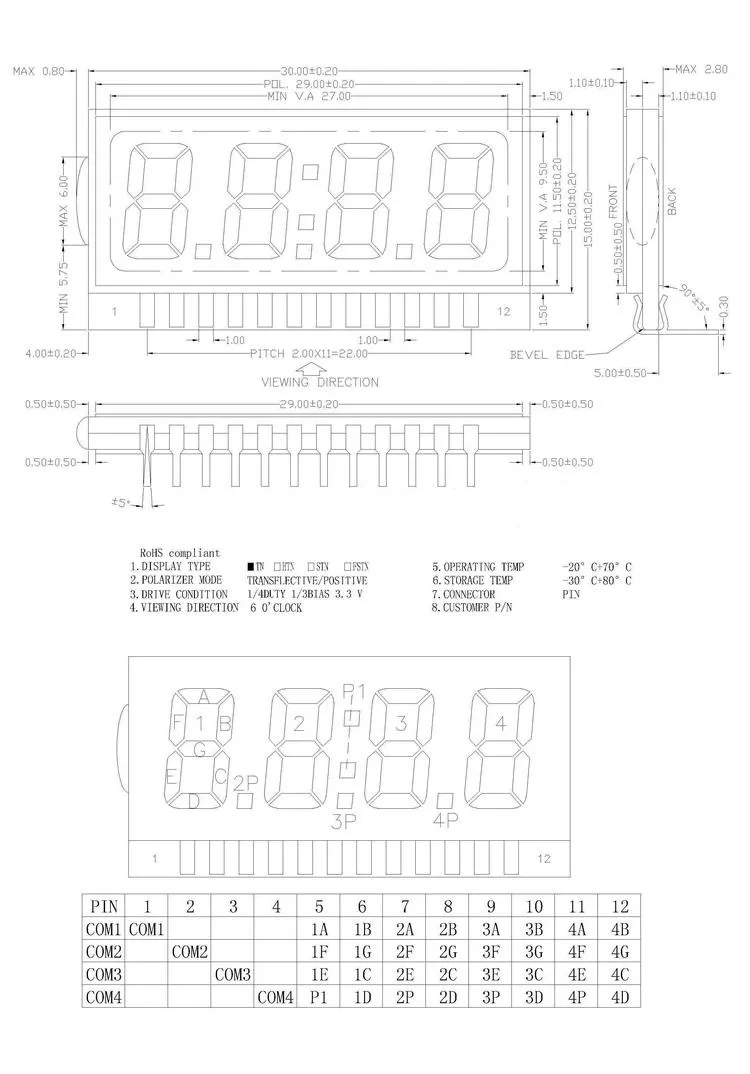
This is a little bit like charlieplexing, take com1 as an example, depend on how the com1 pin is polarized, either segment A or segment B will be turned on, flipping the polarity, the segment that was previously on, will be off, and the other segment that was previously off, now will be on, so to display a digit, it needs to multiplex each of the com pins with twice with different polarity and go through all the four com pins just to display one digit. This is quite different from seven-segment LED, where all the segment of one digit are connected to one common-anode or common-cathode.
The segment LCD has a 20-pin pin header with 2.0 pitch, so it is not breadboard-friendly. As a testing setup, I don't want to solder wire directly to the LCD, I end-up solder a 2.00 pitch header socket direct to my ATtiny3227 board, and plug the segment LCD into the header socket. You can see it in the demo video below. If I need to use the segment LCD in my future project, it will definitely need a custom PCB for the project, or to create a carrier board to have a 20-pin 2.54mm pitch header pin for plug into breadboard.
Through my test, I noticed that there is a mistake about the "specification", the table on the "specification" shown that com1 is connected to segment A and B, but through my test, it shows that it is actually in the reverse order, that is com4 is related to segment A and B, and com1 is related to segment D and all the decimal points and semi-column as shown in the following table. I use this table in my program instead of the one shown on the "specification".
| LCD | 1 | 2 | 3 | 4 | 12 | 11 | 10 | 9 | 8 | 7 | 6 | 5 |
|---|---|---|---|---|---|---|---|---|---|---|---|---|
| PIN | PC3 | PC2 | PC1 | PC0 | PB7 | PB6 | PB5 | PB4 | PB3 | PB2 | PB1 | PB0 |
| COM | COM4 | 4B | 4A | 3B | 3A | 2B | 2A | 1B | 1A | |||
| COM3 | 4G | 4F | 3G | 3F | 2G | 2F | 1G | 1F | ||||
| COM2 | 4C | 4E | 3C | 3E | 2C | 2E | 1C | 1E | ||||
| COM1 | 4D | 4P | 3D | 3P | 2D | 2P | 1D | P1 |
Connection with MCU
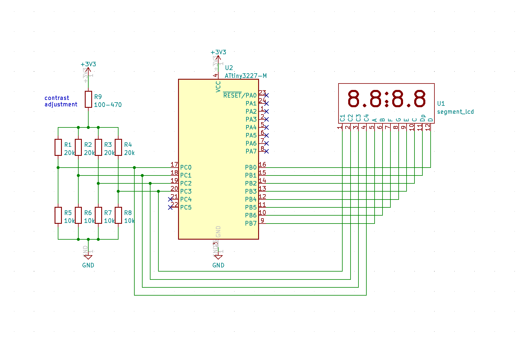
I use an ATtiny3227 as the MCU for driving the segment LCD using GPIOs. This table also shown the GPIO Port and Pins that I used for connecting to the segment LCD.
The R9 on the following schematic provides the contrast control, the value of R1 should be adjusted based on personal preference and expected viewing angle. I noticed that if the value of the resistor is higher than 470-ohm, the display might have difficulty to start-up. The R1 - R8 are 4 voltage dividers that provides the 1/3 bias voltage specified for each com pin. GPIO pins on Port B are used to drive the 8 segmenets, the first 4 GPIO pins on Port C are used to drive the com1 to com4. Since the LCD is a 3.3V device, so the ATtiny3227 should run at 3.3v as well. That's all we need in hardware configuration as shown in the following schematic. The rest will be done in software.
Software
Code is written in bare metal by directly access and control the registers of Port B (for segments) and Port C (for com1 - com4). It however should not be difficult to port it to Arduino framework to run under the megaTinyCore. The demostration code implemented a counter counting from 0 to 9999.
First of all, the clock configuration set the MCU to run at 10MHz instead of 20MHz, this is necessary in order for the MCU to be able to operated at 3.3V or even lower (e.g. coin cell at 3.0V). Periodic Interrupt Timer(PIT - as part of RTC timer) is configured to generate an interrupt in every 2ms (32768Hz/64 = 512Hz or 1/512 = 2ms), which is used to trigger the refresh of the display segment, since there are total 4 com pins, and with two different polarizations, so there are total 2 x 8 = 16 fresh cycles to complete the total display refreshment, or 1/16ms = 62.5Hz refresh rate. This is fast enough that human eyes won't be able to perceive the flicking of the display, and yet not too slow to leave the ghost image between the transistion of the segment from on to off or vice versa.
ISR (RTC_PIT_vect) {
    RTC.PITINTFLAGS = RTC_PI_bm;                      // Clear periodic interrupt flag
    refresh_ready = 1;                                // This is a flag for main loop
}

void pit_init () {
    while (RTC.STATUS > 0);                             // Wait until registers synchronized
    RTC.CLKSEL = RTC_CLKSEL_INT32K_gc;                  // 32.768kHz Internal Oscillator
    RTC.PITCTRLA = RTC_PERIOD_CYC64_gc | RTC_PITEN_bm;  // 32768/64=512, i.e. 1/512=2ms between each interrupt
    RTC.PITINTCTRL = RTC_PI_bm;
}

void main(void) {

    static uint16_t interval_counter =  0;

    _PROTECTED_WRITE(CLKCTRL_MCLKCTRLB, (CLKCTRL_PEN_bm | CLKCTRL_PDIV_2X_gc)); // running at 20/2 = 10MHz
    while (!(CLKCTRL.MCLKSTATUS & CLKCTRL_OSC20MS_bm)) {};
    // _delay_ms(100);

    disableUnusedPin();
    PORTB.DIR = 0xFF;         // set all PORTB(segments) pins as output
    PORTB.OUT = segs_out;     // set all segments to low
    PORTC.DIR = 0x00;         // set all PORTC(COMx) pins as input (high-impedance) for now

    pit_init();

    SLPCTRL.CTRLA = SLPCTRL_SMODE_PDOWN_gc;  // config sleep controller powerdown mode

    sei();

    // LCD refresh
    while (1) {
        if (refresh_ready) {

            refreshSegments();

            interval_counter++;                         // interval_counter increased in every 2ms
            if (interval_counter >= COUNTUP_INTERVAL) { // increment the counter every 2ms * COUNTUP_INTERVAL
                interval_counter = 0;

                LCD_d_1++;                           // 4-digit ripple BCD counter for LCD digits counting from 0000 to 9999
                if (LCD_d_1 >=10) {
                    LCD_d_1 = 0;
                    LCD_d_2++;
                }
                if (LCD_d_2 >=10) {
                    LCD_d_2 = 0;
                    LCD_d_3++;
                }
                if (LCD_d_3 >=10) {
                    LCD_d_3 = 0;
                    LCD_d_4++;
                }
                if (LCD_d_4 >=10) {
                    LCD_d_4 = 0;
                    LCD_d_1++;
                }
            }

            refresh_ready = 0;
        }
        SLPCTRL.CTRLA |= SLPCTRL_SEN_bm;  // sleep enable, this is equivalent to sleep_enable()
        __asm("sleep");                   // this is equivalent to sleep_cpu()
        SLPCTRL.CTRLA &= ~SLPCTRL_SEN_bm; // sleep disable , this is equivalent to sleep_disable()
    }

}
A segment lookup table is used to define what are the segments that need to be turned on or off for each display digit. The segments are not defined in the order of segment A to G like what we normally see in the LED's seven-segment table. It is instead groupped by the segments that are connected to each com pin. With the segment A and B as the two most significant bits, followed by segment F and G, then E and C, and last the Dp(Decimal point) and segment D as the least significant bits.
| Segment | A | B | F | G | E | C | Dp | D |
|---|---|---|---|---|---|---|---|---|
| Digit | COM4-A | COM4-B | COM3-A | COM3-B | COM2-A | COM2-B | COM1-A | COM1-B |
| "0" | 1 | 1 | 1 | 0 | 1 | 1 | 0 | 1 |
| "1" | 0 | 1 | 0 | 0 | 0 | 1 | 0 | 0 |
| "2" | 1 | 1 | 0 | 1 | 1 | 0 | 0 | 1 |
| "3" | 1 | 1 | 0 | 1 | 0 | 1 | 0 | 1 |
| "4" | 0 | 1 | 1 | 1 | 1 | 1 | 0 | 1 |
| "5" | 1 | 0 | 1 | 1 | 0 | 1 | 0 | 1 |
| "6" | 1 | 0 | 1 | 1 | 1 | 1 | 0 | 1 |
| "7" | 1 | 1 | 0 | 0 | 0 | 1 | 0 | 0 |
| "8" | 1 | 1 | 1 | 1 | 1 | 1 | 0 | 1 |
| "9" | 1 | 1 | 1 | 1 | 0 | 1 | 0 | 1 |
Let's assumed that we'd want to display "0123" on to the display, digit "0" is the left most digit (i.e. digit for 1,000) and digit "3" is the right most digit (i.e. digit for 1). We will first use the lookup table to get the segment values for each display digit, but this value can't be directly used to drive the LCD segments. We need to create a segs_out value that is the combination of all the segment A and B of each of the four digit, then set the com4 to OUTPUT and output the value of segs_out, segment A and B can then be turn on or off by altering the com4 pin to refresh the two segments in two refresh cycles.
On the subsequent fresh cycles, we will create the segs_out value for segment F and G, and repeat the process by setting com3 LOW and HIGH to refresh the segment F and G of all the digits.
The process get repeat for com2, then com1, it takes a total of 16 fresh cycle to fresh the display completely.
void refreshSegments() {
    segment++;

    if (segment > 7) {
        segment = 0;
    }

    // The following segment generates the 4 COM output waveforms via PORTC, each with HI and LOW outputs
    // PORTB for segment pins.
    switch (segment) {
        case 0:
            segs_out  = (segment_table[LCD_d_1] & 0x03);      // get digit_1's B & A bits
            segs_out |= (segment_table[LCD_d_2] & 0x03) << 2; // get digit_10's B & A bits
            segs_out |= (segment_table[LCD_d_3] & 0x03) << 4; // get digit_100's B & A bits
            segs_out |= (segment_table[LCD_d_4] & 0x03) << 6; // get digit_1000's B & A bits
            PORTC.DIR = 0;                                    // set all com pins to input
            PORTC.OUT = 0;
            PORTB.OUT = segs_out;
            PORTB.DIR = 0xFF;                                 // set all segment pin to output
            PORTC.DIRSET = PIN0_bm;                           // COM4 asserted LOW
            break;
        case 1:
            PORTC.OUTSET = PIN0_bm;
            PORTB.OUT = segs_out ^ 0xFF;                      // reverse segment outputs
            PORTB.DIR = 0xFF;                                 // set all segment pin to output
            PORTC.DIRSET = PIN0_bm;                           // COM4 asserted HIGH
            break;
        case 2:
            segs_out  = (segment_table[LCD_d_1] & 0x0c) >> 2; // get digit_1's G & F bits
            segs_out |= (segment_table[LCD_d_2] & 0x0c);      // get digit_10's G & F bits
            segs_out |= (segment_table[LCD_d_3] & 0x0c) << 2; // get digit_100's G & F bits
            segs_out |= (segment_table[LCD_d_4] & 0x0c) << 4; // get digit_1000's G & F bits
            PORTC.DIR = 0;
            PORTC.OUT = 0;
            PORTB.OUT = segs_out;
            PORTB.DIR = 0xFF;                                 // set all segment pin to output
            PORTC.DIRSET = PIN1_bm;                           // COM3 asserted LOW
            break;
        case 3:
            PORTC.OUT = PIN1_bm;
            PORTB.OUT = segs_out ^ 0xFF;                      // reverse segment outputs
            PORTB.DIR - 0xFF;
            PORTC.DIRSET = PIN1_bm;                           // COM3 asserted HIGH
            break;
        case 4:
            segs_out  = (segment_table[LCD_d_1] & 0x30) >> 4; // get digit_1's C & E bits
            segs_out |= (segment_table[LCD_d_2] & 0x30) >> 2; // get digit_10's C & E bits
            segs_out |= (segment_table[LCD_d_3] & 0x30);      // get digit_100's C & E bits
            segs_out |= (segment_table[LCD_d_4] & 0x30) << 2; // get digit_1000's C & E bits
            PORTC.DIR = 0;
            PORTC.OUT = 0;
            PORTB.OUT = segs_out;
            PORTB.DIR = 0xFF;
            PORTC.DIRSET = PIN2_bm;                           // COM2 asserted LOW
            break;
        case 5:
            PORTC.OUT = PIN2_bm;
            PORTB.OUT = segs_out ^ 0xFF;                      // reverse segment outputs
            PORTB.DIR = 0xFF;
            PORTC.DIRSET = PIN2_bm;                           // COM2 asserted HIGH
            break;
        case 6:
            segs_out  = (segment_table[LCD_d_1] & 0xC0) >> 6; // get digit_1000's DP & D bits
            segs_out |= (segment_table[LCD_d_2] & 0xC0) >> 4; // get digit_100's DP & D bits
            segs_out |= (segment_table[LCD_d_3] & 0xC0) >> 2; // get digit_10's DP & D bits
            segs_out |= (segment_table[LCD_d_4] & 0xC0);      // get digit_1's DP & D bits
            PORTC.DIR = 0;
            PORTC.OUT = 0;
            PORTB.OUT = segs_out;
            PORTB.DIR = 0xFF;
            PORTC.DIRSET = PIN3_bm;                           // COM1 asserted LOW
            break;
        case 7:
            PORTC.OUT = PIN3_bm;
            PORTB.OUT = segs_out ^ 0xFF;
            PORTB.DIR = 0xFF;
            PORTC.DIRSET = PIN3_bm;                           // COM1 asserted HIGH
            break;
        default:
            PORTB.DIRCLR = 0xFF;                              // clear all pins
            PORTC.DIRCLR = 0xFF;                              // COM1-COM4 float
    }

}
The demonstration code implement a 4-digit ripple BCD counter that count up from 0000 to 9999 in every 200ms which is determined by the interval_counter which increment every 2ms as per each freshment cycle. When it reaches to the value set by COUNTUP_INTERVAL (default to 100), the display counter is incremented by 1, that is, the count-up counter on the display is counting up in every 2ms x 100 = 200ms.
Battery Consumption
The demonstration code utilizes ATtiny3227 Power Down sleep mode to keep the overall power consumption as low as possible. All the unused GPIO pins are disabled during the initialization stage. The PIT interrupt is the only one that can be wake-up during Power Down sleep mode, the code basically wakeup every 2ms, fresh a segment and go back to sleep mode.
The battery consumption for both ATtiny3227 and LCD is at about 3.5mA when running at 10MHz clock without deep sleep. The battery consumption drops to approximated 585uA with Power Down deep sleep implemented. As the mojority of the 585uA sleep current is due the four 30k-ohm voltage dividers used to generate the 1/3 bias voltage, which collectively has a total resistance of 7500-ohm across the power source, contributing 3.3v/7500ohm = 440uA to the overall sleep current. The sleep power consumption can be further reduced by using higher resistor values for the voltage divider.
Summary
With limited information available and it tooks a little bit of try-and-error, but I'm glad that I figure out how to bit-banging the segment LCD. It was an impulse buy on Aliexpress out of curiosity, and I don't really has a specific project to use the segment LCD yet, but I'm sure that I will use it in suitable future project with this LCD display.
Despite nowadays OLED and TFT display is popular and LCD display is slowly fading away compare to just 10 years ago, but I like LCD over OLED for one simply reason, that is, they have very low power consumption, making it the idea choice for battery-operated project with small and simple screen. So in many of my projects, if the project requires battery operation, I would tend to use LCD display over OLED. For simple seven-segment display, LCD segment display would be much compact in size and less power hungry than seven-segment LED.
Github
The complete source code is available at my github repository Segment LCD.
Demo Video
Here is a quick Youtube video demostration of the segment LCD driven by an ATtiny3227 running at 3V at internal clock speedd of 10MHz.