It is important to understand how SPI (Serial Peripheral Interface) works in the embedded world because SPI is widely used deep inside embedded systems, ranging from sensor connection, to SD card interface, to even between the flash memory and its MCU.
What is SPI?
The name imply that it is a Serial communication protocol and interface, but it is different from serial communication protocol like UART in many different aspects. SPI is simpler in design compared to UART. UART uses two wires for transmission and reception (Tx and Rx), and requires a clock on both sides to be on the same speed, UART is designed for long range communication, both hardware and software flow control can be added if necessary. In order to ensure the integrity of the data, simple parity check can be introduced into the communication stream as well.
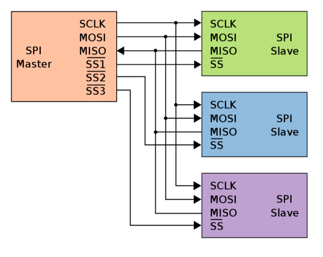
SPI is gnerally designed for high-speed, shorter range of communication at a clock speed set by the data initiator (i.e. the Master) and therefore does not need the checksum bits. This allows SPI to be run at higher data speed and easy to use once it is setup. SPI is more than just a serial communication protocol, it is a bus with master and slaves connecting on the same communication bus. This allows one master to communicate with one or more slaves. Each SPI bus requires 4 wires between master and slave.
- MOSI: Master-Out-Slave-In for master to send data to a slave;
- MISO: Master-In-Slave-Out for master to receive data from a slave;
- SCLK: A Serial Clock tat regulates the speed of the communication;
- SS: Slave Select to select the peripheral device/component.
The slave devices on the SPI bus will always receive the SPI clock signal, but will not respond to the SPI master until their respective Slave Select line has been activated (i.e. SS go active LOW). This allows multiple peripherals to be connected on the same bus that share the lines of MOSI, MISO and SCLK, and each peripheral has its own SS line, and only the peripheral that has its SS been pull low to listen to the communication sent by the master.
Data transfers between master and slave devices on the SPI bus are handled by separate transmit and receive FIFO (First-In-First-Out) buffers. The SPI module works in Full-Duplex mode, meaning that during each clock cycle, the SPI module is simultaneously transmitting via MOSI and receiving data via MISO from the activated slave. This bit-wise exchange of data will continue until there is no more data to be exchanged or an interrupt occurs, at which point the master will stop sending clock signals to the slave.
Arduino SPI
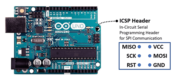
The SPI bus on Arduino varies depend on the model of Arduino board. For ATMega328p-based Arduino boards (i.e. Uno, Nano and Pro Mini), it has pin 11, 12 and 13 as SPI's MOSI, MISO and SCLK signals, but at the same time these signals are also available on those board's In-Circuit Serial Programming (ICSP) header pin 4, 1 and 3, except for Pro Mini which does not have a dedicated ICSP header. This however is not the case for Arduino Leonardo and Arduino Micro which are based on ATMega32U4, for those boards, the SPI is only available on ICSP header. This is one of the reasons that some of the Arduino shields designed for Arduino Uno does not work with Arduino Leonardo when SPI communication is involved. The ICSP interface however does not expose the SS line. By default, on most of the Arduinos, SS is defined to be on pin 10, and on the Arduino Mega2560, it is on pin 53.
Arduino SPI Library
Most of the Arduino SPI implementations utilises the standard SPI library provided by Arduino. The library provides sufficient abstraction to make SPI programming really easy to use. But there are a few things need to be awared.
SPI Library only support Master mode
The SPI library only supports master mode, if you need to use the Arduino as a slave, you will probably need to write your own driver or library (we will discuss this later). This is also why it is important to initiate the SS line as OUTPUT, if you set the SS line as INPUT, it will automatically put the Arduino into slave mode, and there is no code in the Arduino SPI library that could handle the case when Arduino is in slave mode.
Define your own SS pin on some of the boards
There is no pre-defined SS pin for Arduino Leonardo, and most of the non-AVR boards, such as Due(which is based on SAM3X8E MCU), and SAMD21-based boards like Zero or Nano 33 IoT, but really any digital GPIO can be used as SS pin, you just need to configure a digital I/O pin as OUTPUT and set it to HIGH for idle stage, and use it as SS.
You must call SPI.begin() to initialise the SPI interface before using it. The SPI.begin() sets the SCLK, MOSI, and SS pins to OUTPUT, and pulling SCLK, MOSI LOW, and SS HIGH.
#define SS 10   // define your own SS pin for Leonardo or any non-AVR Arduino boards

void setup() {
    pinMode(SS, OUTPUT);
    digitalWrite(SS, HIGH);    // always set SS HIGH
    SPI.begin();    // initialise SPI pins
}
SPI Configuration
There are three parameters would needed to be setup prior transfering data over the SPI bus.
The master is the device that generates the system clock and decides when to trigger communication. The clock frequency is derived from the main clock of the microcontroller and is reduced using a prescaler or divider within the MCU to the expected clock speed. For Arduino library, the speed is give as an ordinary number, expressing in Hz the maximum clock speed that device can use. The SPI library will automatically select the fastest clock available which is equal or less than your number. This allows your code to always use the best speed. Unless you want to specifially assign a clock speed that you want your SPI device to operate at, it is generally a good idea to set the maxium clock speed to equal to the MCU clock speed, in the case of AVR-based Arduino, it is 16MHz (16000000).
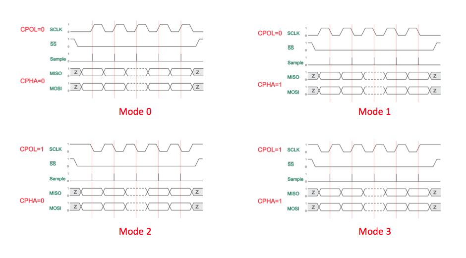
The second parameter required has to do with the concept of SPI mode. In the Arduino library, ther are 4 pre-defined constants that represents the 4 SPI modes, it is defined as SPI_MODE0, SPI_MODE2, and SPI_MODE3. In many datasheet of SPI devices, the SPI modes are often shown as a combination of SCLK Clock Polarity(CPOL) and SCLK Phase (CPHA). The CPOL indicates the idle stage of the SCLK, and the CPHA describes at what clock phase (or edge) that the data is going to be shifted into the FIFO register (transit stage) and when the data is ready to be captured. The following table provides the information of 4 SPI modes.
| Mode | SCLK Polarity (CPOL) | SCLK Phase (CPHA) | Data Transit on | Data Capture on |
| SPI_MODE0 | 0 | 0 | Falling edge | Rising edge |
| SPI_MODE1 | 0 | 1 | Rising edge | Falling edge |
| SPI_MODE2 | 1 | 0 | Rising edge | Falling edge |
| SPI_MODE3 | 1 | 1 | Falling edge | Rising edge |
A clock signalling diagram provides better picture on the 4 SPI modes. The beginning of the diagram indicates whether the SCLK at idle stage is LOW (CPOL=0) or HIGH(CPOL=1). The red line indicates at which clock phase or edge that the data will be captured. CPHA=0 means that data will be captured at the rising edge, and CPHA=1 means that data will be captured at the falling edge(CPHA=1) of the SCLK.
The last configuration parameter required is whether the SPI device's FIFO buffers will send the Most Significant Bit (MSB) first or the Least Significant Bit (LSB) first.
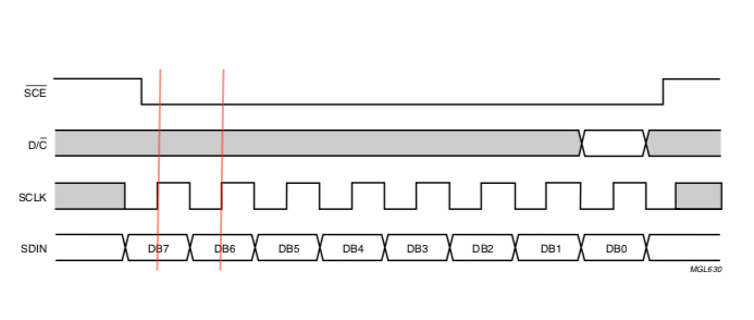
Both of those information can be found in the datasheet of any SPI device that you are trying to interface with. For example, the picture below is from the PCD8544 datasheet that is used by commonly available Nokia 5110 LCD Module. The pictue shows that PCD8544 is operated at SPI_MODE0 and data is sent with MSB first.
SPI library make setting those parameters real easy by creating an SPISettings object and pass it into SPI.beginTransaction() prior transfering the data. SPISettings object consists of 3 parameters, the first parameter is the maximum speed of the SPI SCLK, the second parameter is the bit order (MSBFIRST or LSBFIRST), and the third parameter is the SPI mode (SPI_MODE0, SPI_MOD1, SPI_MODE2, and SPI_MODE3). By default, if you don't pass in any parameter to the SPISettings, it will set the clock speed to 4MHz, operate on SPI_MODE0 mode with MSB to be sent first. So:
SPISettings mySettings();
is equivalent to:
SPISettings mySettings(4000000, MSBFIRST, SPI_MODE0);
Instead of creating an SPISettings object separately, you could using the inline style by creating the SPISettings object when calling the SPi.beginTransaction() function.
SPI.beginTransaction(SPISettings(4000000, MSBFIRST, SPI_MODE0));
The SPI.beginTransaction() is not just create the SPI transmission configuration, it is also gain exclusive access to the SPI bus, and therefore it is important to release it after data transfer with SPI.endTransaction(). By passing in the SPISettings during each transaction allows each transaction or SPI device to have its own configuration setting.
SPI Data Transfer
Your already know the SPI.begin() and SPI.beginTransaction(), a typical use of SPI data communication looks like this:
SPI.beginTransaction(SPISettings(14000000, MSBFIRST, SPI_MODE0));    //initialises SPI clock speed, mode and bit order
digitalWrite(SS, LOW);    // select slave
SPI.transfer(mybyte1);    // transfer data
SPI.transfer(mybyte2);    // if there are more data to be transfered
digitalWrite(SS, HIGH);   // deselect slave
SPI.endTransaction();     // this allows other to use the SPI bus
Depend on the data to be transfered, there are a few data transfer methods that you could call:
uint8_t dataByte = 0x48;
uint8_t receivedVal = SPI.transfer(dataByte);     //send one byte over SPI

uint16_t dataInt = 32768;
uint16_t receivedInt = SPI.transfer16(dataInt);    // send 16-bit unsigned integer

char buffer[12] = "Hello World";
const int size = strlen(buffer);
SPI.transfer((uint8_t)buffer, size);    // send all the data in a buffer array to the slave
SPI transfer is based on a simultaneous send and receive: the received data via MISO is returned as receivedVal (or receivedInt). In case of buffer transfers the buffer will now contained the received data from MISO. It is important to allocate sufficient buffer size to avoid data overflow.
The SPI.endTransaction() allows other devices to use the SPI bus, if interrupt is used, it will also re-enable the interrupt.
Do and Don't of Using SPI library
The first one that I'm going to talk about is not a clear Do or Don't but should be avoid unless you know what you are doing and it is really necessary.
Do use SPI.beginTransaction()
Transactional SPI using SPI.beginTransaction() was introduced in 2014, it was not available in the early version of the Arduinos or example codes published before that. As the results, there are still many codes out there on the Internet show the old way of setting up the SPI configuration, and this include the exampes provided by stardard Arduino AVR Core and Arduino.cc library reference page even up to today, the authors of the library did not make any changes in those examples to show the usage of new API.
What the SPI.beginTransaction() does is to allow you to set unique SPI settings for your application, even if other devices use different settings. SPI.beginTransaction() provides better cross-device compatibility and solve software conflicts and allowing multiple SPI devices to properly share the SPI bus. You should therefore use the SPI.beginTransaction() in your SPI sketch.
There is a pre-defined macro SPI_HAS_TRANSACTION in SPI library for checking whether the firmware of the Arduino board supports SPI.beginTransaction(). It is useful for providing backward compatibility if you are writing an Arduino library.
#ifdef SPI_HAS_TRANSACTION
  SPI.beginTransaction(SPISettings(4000000, MSBFIRST, SPI_MODE0));
#elseif
  // use old Arduino SPI library syntax
#endif
Don't use the deprecated methods
If you look at many legacy example codes on the Internet, you will find several optinal methods SPI.setBitOrder(), SPI.setClockDivider() and SPI.setDataMode() used for confiuring the SPI. Do not use those methods as those methods have been depreciated since 2014, although those methods are kept in the library for backward compatibility purpose. You should use the SPISettings object to configure your SPI communication interface as we discussed.
Do add pull-up resistors on SS or set SS HIGH for multiple-slave system
When multiple SPI devices are used, and especially when some of the slaves are not coded by your system, pullup resistors are needed on the chip select pins. Alternatively you should set all the SS lines HIGH at your setup() prior the SPI.begin() is called, as we shown previously. This will ensure that all the SS lines stay HIGH when the devices are not been called.
Without a pullup resistor, the SS line might be neither LOW nor HIGH, this might caused some of the devices on the bus to “hear” the communication on its MISO that was not intend for the device. This might explained why some of the Arduino shields or breakout boards with SPI works when used alone, but fail when used together with other SPI boards, causing by some of those boards lack of pullup resistor or the user didn't pull all the SS lines in the system HIGH at the setup() before calling the SPI.begin()!
Do ensure MISO can be tri-state in multiple-slave system
Most SPI chips will be at tri-state on their MISO pin when their chip select signal is HIGH. Tri-stage means that it is neither HIGH nor LOW (i.e. floated) and effectively disconnect. However, it is not always the case. A SPI device without tri-state MISO could caused potential problem on a SPI bus where multiple SPI devices are connected. If the MISO is unable to be at tri-state, it will be either HIGH or LOW, this will affect other devices connected on the same bus in receiving data.
Paul Stoffregen (the creator of Teensy Arduino-compatible boards) points out one example of using tri-state buffer as well as on how to verify SPI device's MISO tri-state on his "Better SPI Bus Design in 3 Steps" article (link provided below under Reference).
Arduino as an SPI Master
Enough talking, let's put what we discussed so far together as a complete Arduino sketch for as a SPI master. To make the thing a little bt more interesting and more chanllenging, let's see how to send a floating point number over SPI. In Arduino, floating point are a 32-bit data structure, and SPI is sending data byte by byte.
arduino_spi_master.ino
#include <SPI.h>
void setup() {
Serial.begin(115200);
Serial.println("\nSPI Master");
SPI.begin();
}
void loop() {
float pi = 3.14159;
uint8_t *ptr = (uint8_t *)π //cast the address of a float into a pointer of byte
SPI.beginTransaction(SPISettings(4000000, MSBFIRST, SPI_MODE0));
digitalWrite(SS, LOW);
for (int i=0; i<sizeof(pi); i++) {
SPI.transfer(*ptr); // send the pi byte by byte
Serial.print(*ptr); // for debugging, print out each byte
Serial.print(", ");
*ptr++;
}
digitalWrite(SS, HIGH);
SPI.endTransaction();
Serial.println();
delay(5000);
}
We can easily know where the floating point value pi stored with &pi, this however is pointed to a floating point which is 4-byte in Arduino. We need to cast the address into a pointer for byte (i.e. uinit8_t) so that we can access the data byte by byte. We covered the rest of the code in our previous discussion so I won't repeat it here again. In order to demonstrate what we sent get received at the SPI slave correctly, we need to have a SPI slave to receive it and display it as a floating point.
Arduino as an SPI Slave
As mentioned previously, SPI.h library by default only support Master mode, the SPI.begin() will automatically set slave select (SS) pin to HIGH whether you have pinMode(SS, OUTPUT) in setup() code or not and set the Arduino as an SPI master. This can be see on SPI library source code.
As the SPI library does not contain the functionality for SPI slave mode, in order to use Arduino as a SPI slave, we will need to write our own customised setup, mainly on:
- Setting MISO as OUTPUT for slave to send data;
- Enable slave mode by directly setting the SPCR(SPI Control Register);
- Enable interrupt to receive data.
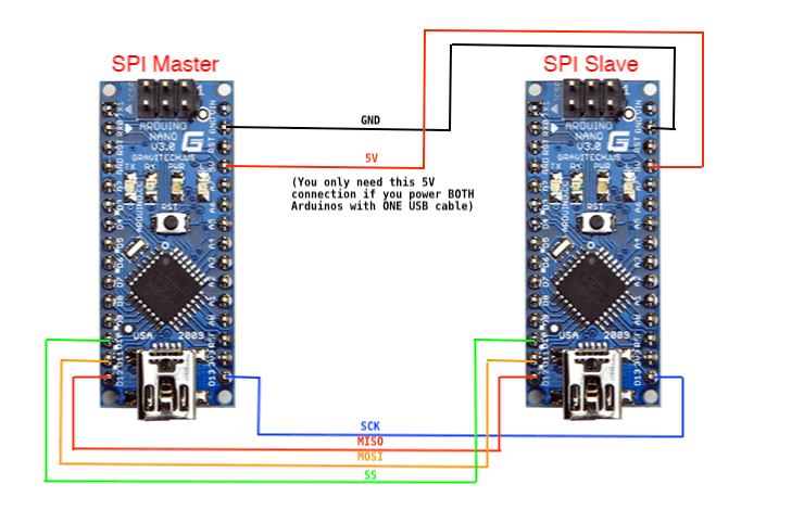
To demostrate this, you will need to have two Arduinos (I used Arduino Nano) connected together to form a SPI bus network, with one Arduino running as SPI Master, another running as SPI Slave.
Here is a sketch for SPI Slave that will receive the floating point data send from the SPI Master that we previously written.
arduino_spi_slave.ino
#include <SPI.h>

volatile uint8_t byteCount = 0;
volatile bool dataReady = false;

float data;
uint8_t *ptr = (uint8_t *)&data;

// SPI interrupt routine
ISR (SPI_STC_vect) {
  ptr[byteCount++] = SPDR;    //read one byte form SPI Data Regiser
  if (byteCount == 4) {
    dataReady = true;
  }
}

void setup (void) {
  Serial.begin(115200);
  Serial.println("\nSPI Slave");
  SPCR |= bit(SPE);        // enable SPI slave mode
  pinMode(MISO, OUTPUT);   // set MISO as OUTPUT
  SPI.attachInterrupt();
}

void loop (void) {
  if (dataReady) {
    Serial.println(data, 5);
    byteCount = 0;    // reset byteCount and dataReady flag
    dataReady = false;
  }
}
The SPCR |= bit(SPE) set the SPE bit of SPCR of ATmega328 MCU (used by Arduino Uno, Nano and Pro Mini) to 1, this enable the SPI and set the SPI to slave mode, the discussion of how MCU registers work is out of the scope of this article, but if you are interesting to learn more, you can read the entire section 19 about SPI or section 19.5 of ATmega328P data sheet on how to use the registers for SPI configuration. Since we are operating in slave mode, therefore MISO is an output for slave to send data, so we uses pinMode(MISO, OUTPUT) to set the MISO line as OUTPUT.
The setup() also enable the SPI interrupt so that when a byte of data is received via SPI, the ISR() (Interrupt Subroutine Function) will be triggered, which will get the data from the SPDR (SPI Data Register) and since we are expecting a floating point data, the ISR is written in such a way that we uses a byteCount to check if 4 bytes data have been received, and if yes, the ISR will set the dataReady state to true. All the loop() function needs to do is to see if the dataReady state is true, and if it is, simply print the received data as a floating point.
Please noted that since different MCU has different register structure and naming convention, this code only works for those Arduino with ATmega328P MCUs, for MCU other than ATmega328p, you will need to check the data sheet of the MCU to port it to other MCU.
Although this code demostrate on how to send a floating point, it is easy to conver it to send string/array or integer once you understand on how to send floating point.
Next Step
We used two Arduino connected together to demonstrate the SPI Master/Slave operation between two Arduinos. In most of application, you will likely using the SPI to communicate with some chips or modules that utilized SPI interface. With what you learnt so far, together with a datasheet of the SPI device you are dealing with, you should be able to write your own SPI application or driver for any SPI device. How to use LCD5110(PCD8544) with Arduino shows how to write a LCD driver for commonly available Nokia 5110 LCD module based on datasheet of PCD8544 chip that is used in the module, it is a good example on how to apply what you learn here to actual code.
References
This article is the results of hours of research, reading of source codes, datasheets and actual usage experiences. Among all the information available on the Internet, here are several links that provided good references on the subject.
SPI library, Arduino.cc
SPI library source code, ArduinoCore-avr github
Serial Peripheral Interface, wikipedia
Better SPI Bus Design in 3 Steps, Paul Stoffregen
How do you use SPI on an Arduino, Nick Gammon
Great summary article – detailed, thorough, comprehensive — very helpful!
I have a couple of projects which are both duplicates based on the Mega2560 and see the Due with the 512k, this looks like the same form factor as the Mega from what I see on my screen. Is this correct? Also it looks like the memory is twice the size which would be a nice upgrade. I don’t have that much experience with Arduino but I’m trying to learn how they work and the Due without the headers and some other features looks like it would be a better choice for my projects as it could be made a permanent part of the expansion system the Mega is for. I have one original Mega and a clone that I’m trying to get programmed for the projects, if the Due will work I will purchase a couple of those and keep my Megas for other stuff.
This is a page about SPI, so I’m not quite sure how this is related to your question? But if you are asking the difference between Mega2560 and Due, they are architecturally different, Mega2560 is a 8-bit AVR MCU, and Due is using a 32-bit ARM MCU. However, both can be run on Arduino IDE, as Arduino IDE supports various MCUs with different architecture by installing additional Core software. You might want to read Installing the SAM core for the Arduino Due for more details.