I recently build myself a Li-Ion/Li-Po battery capacity tester, this article discuss the theory behind a battery capacity tester and how I build it.
On my previous blog I mentioned that I often salvage 18650 batteries or other Li-Po battery packs from old appliances. One thing about those salvaged battery is that sometime those batteries were not marked with its battery capacity information. Even when it is marked, as it has been used for sometime, the battery capacity might be as it shown. In either case, it is important to know the battery capacity.
Theory
The unit of a battery capacity is mAh or Ah. When a battery is marked with, say, 2400mAh on it, bsically what this means is that, if we connect a load across it which draws 2.4A then this battery would last for an hour. Similarly, if a load is drawing 600mA, it is then supposed to last 4 hours. So theoritically, all we need is to know the current a load is drawing from a battery and meausre the time from the begin till the battery went flat, we will get the battery capacity by times the discharge current with the discharge time to come out the mAh value which represents the battery capacity.
But it is not pratical to calculate the capacity this way, when a Li-Ion/Li-Po battery is fully charged, it will have a voltage of 4.2V, during the discharge period, the voltage is dropping gradutually, and so is the current, therefore in order to calculate the battery capacity, we will need a constant current source so that the current (i in mA) will remain constant throughout the discharging period (h in hour), and we measure how long it take for the batery to gradually decrease from fully charged 4.2v to a cut-off voltage of say 2.5v, we then have the capacity by simple multification i with the accumulated discharging time h.
Hardware
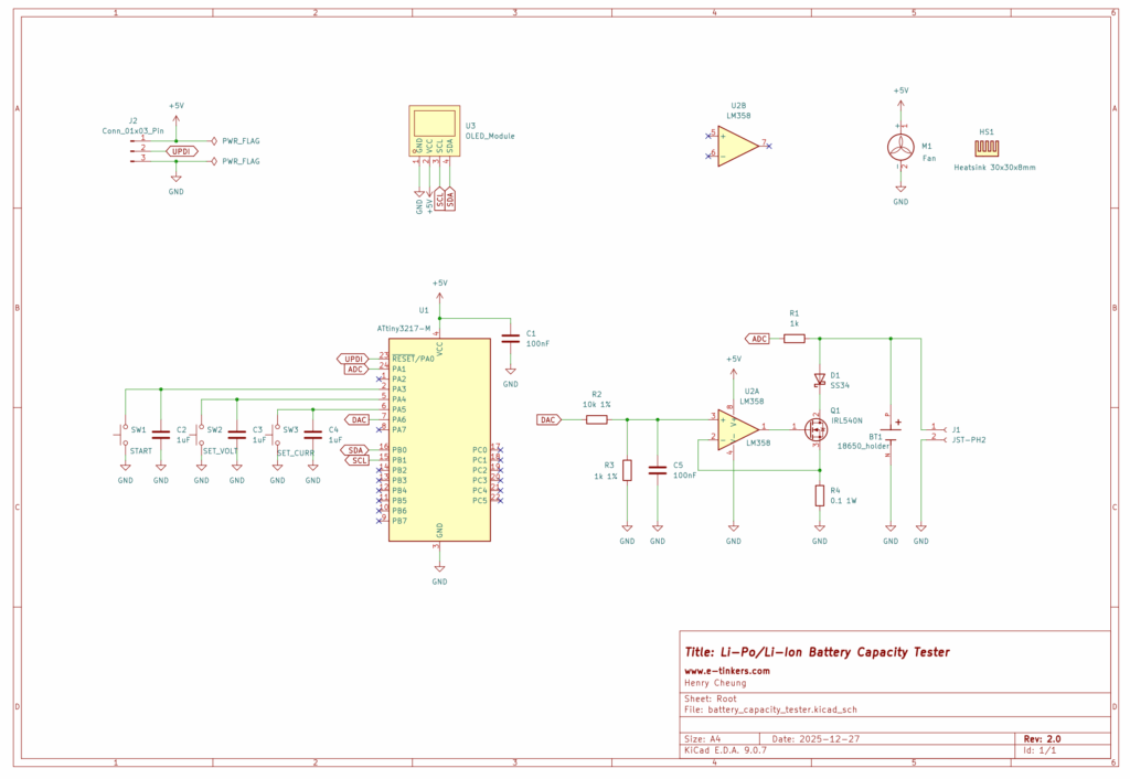
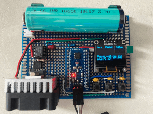
The schematic can roughly breakdown into two part, the constant current circuit and microcontroller (together with display and switches for user interface).
THe constant current source consists of an LM358 operational amplifier (OpAmp), an IRL540N MOSFET and a 100mΩ/1W shunt resistor (R4). If the battery is discharged at 1A via the MOSFET and the shunt resistor, the voltage drop at the shunt resistor whould be 1A x 0.1-ohm = 0.1V, the shunt resistor is also connect to the inverting input pin of the OpAmp, the non-inverting input pin of the OpAmp is feed from the DAC output of a Microprocessor via a voltage divider R2 and R3. By adjusting the DAC output, it controls the voltage output of the OpAmp comparitor and therefore the current flow through the MOSFET, to ensure the current remains constant throughout the discharging period. The voltage of the battery is read by an ADC of the microprocessor and used its value to determine what voltage should be set as the output of the DAC to drive the MOSFET.
When I research the project through internet, I found there are a lot of various implementation using Arduino Nano or Uno, which does not have an internal DAC peripheral, so a PWM pin is used to generate a waveform and then go through some low-pass filter to come out a DC voltage as a cruel DAC. This is not ideal, and modern AVR chip such as ATtiny 1-series has a build-in DAC, so I decided to use ATtiny3217 as the microprocessor instead of the popular ATMega328p found in Arduino Uno or Nano.
A 0.96" OLED display is connected to the microprocessor via I2C as a user interface which makes the controlling/adjustments easy. The display provide the current, voltage measurements and the elapsed time as well as the calculated battery capacity in real time.
Three tactile push buttons are connected to three different GPIO pins that are configured as digital input with internal pull-up resistors enabled. SW2 is used to set the cut-off (termination) voltage (SET_VOLT), SW3 is used to set the discharge current rate (SET_CURR). SW1 (START) is used for starting the battery discharge process.
Since I only need one battery capacity tester, so it doesn't make sense to go for PCB fabrication, I have a number of 7x9cm prefboards with me and it turns out to be perfect for the project.
Although the schematic shows the user of a bare ATtiny327 chip, but in actual implementation I use a readily-made ATtiny3217 Development Boards that I produced in 2020, which makes it easier to directly solder the header pins of the development board to the Prefboard. The OLED module is also directly solder to the Prefboard. The distance between the two battery holder plates are positioned in such a way that it capacble to be used for non-protected 18650 battery as well as the retrofited protected 18650 (which is slightly longer than 6.5cm) that I discussed on the previous project. A JST-PH2 socket is also available in case I need to test other battery pack that has the JST connector.
The IRL540N is not only control the current through its internal resistance, it is effectively a controllable dummy load in this application, so it could getting hot depends on the discharging current. I purchase a 5V 30x30x10mm Fan with an 30x30x8mm heatsink attached to the fan from AliExpress and mounts the IRL540N on the heatsink to keep the MOSFET temperature down.
You might already noticed that there is no power supply or voltage regulator in the schematic. I power the tester from my bench power supply via the header pins (which also include UPDI pin for upload the firmware) on the ATtiny3217 Dev Board whenever I used it.
Software
To use the battery capacity tester, power the tester with a 5V power supply, select the Battery discharge termination (cut-off) voltage and the battery discharge current rate, insert the battery under test, and press START.
It is important to fully charge the battery first before testing.
When the board is power-up, the software set the cut-off voltage of 2.5 volts as default, and the battery discharge current at 200mA. User can press SW2 (SET_VOLT) button to select cut-off voltage between 2.5 volts and 3.2 volts at an increment of 0.1 volts. Likewise, user can press SW3 (SET_CURR) button to select constant discharge current betwen 200mA and 2000mA with increment of 100mA.
Although the CURR_MAX macro in the software is hardcoded and set to 2000, it is possible to modified it to a maxium of 3000 (i.e. 3A) but should never set beyond 3000 as the average forward current that the SS34(D1) in the schematic is 3A.
For those betteries with built-in protection circuit, it is important to get to know the battery cut-off specification before setting the cut-off voltage, some battery use a protection circuit that has cut-off of 2.9V but many have cut-off as low as 2.5V.
There will be no output on DAC until the user pressed START button. When user presses the START button, DAC is initialized, and the output voltage is calculated based on user's selection of discharging current. To maximize the accuracy of the DAC output voltage, ATtiny3217 has an internal reference source (VREF) that can be select betwen 500mV, 1.1V, 1.5V, 2.5V and 4.3V, the appropriated VREF setting is selected by the software during the DAC initialisation based on the discharging current. For example, if the discharging current is 200mA, the voltage across the shunt resistor will only be 20mV, that means the DAC output from the MCU (i.e. before the voltage divider) should be at 220mV, and therefore it make sense to use VREF of 500mV. Likewise, if the user set discharging current to 2A, the voltage across the shunt resistor would be 200mV, and DAC output should therefore be 2.2V, so it make sense to set the VREF to 2.5V.
For ADC configuration, however, VREF of 4.3V is set as a Li-Ion/Li-Po battery could be between 2.5V and 4.2V. The ADC is configured to accumulate 64 samples and return the average result for providing stable reading of the battery voltage.
The battery voltage is first read through ADC without the load before the DAC is configured (i.e. MOSFET is off, or without the load), and another reading is obtained right after the user pressed the START to kick start the discharging process. The differences between these two ADC values are used to caulcate the internal battery resistance which represents the healthness of the battery, and the internal battery resistance value is displayed on screen in milli-ohm.
Timer/Counter B (TCB) is used to generate an accurate milli-second counter for time tracking purpose.
Once the battery reaches to the discharge cut-off voltage, the program will stop and the result battery capacity is displayed on the screen in mAh and mWh.
Disclaimer
I did not design the hardware and write the software completely by myself from scratch. A very significant part of the hardware design and the software is based on Stefan Wagner's ATtiny412 Battery Capacity Tester. However, I modified both the hardware design and re-write some of critical part of the software algorithm on determine the discharging current, also found a few bugs and submitted my pull requests to Stefan here and here. I must say that without Stefan's design, it would take me much longer to do the project, so Thank you Stefan, and very much appreciated for his effort and contribution to the open source hardware and software.
Here are the main changes on both hardware and software from the original design.
Hardware Modification
- Use ATtiny3217 instead of ATtiny412
- Use LM358 instead of LMV321
- Connect 3 buttons directly to 3 GPIO pins instead of using ADC ladders for buttons
- Use Prefboard instead of fabricating a PCB
- Battery holder supports both non-protected 18650 and protected 18650 batteries
- Add JST connector for Li-Po/Li-Ion battery pack supports, remove the support on CR123A
Software Modification
- Modified the code to connect each button to a GPIO pin instead of using ADC pin
- Remove some magic numbers in the code and replace with #define macros
- Rewrite DAC_init() and only be called after user selected cut-off voltage
- DAC_setLoad() no longer need and integrated into DAC_init()
- Re-arrange the display information and prompts to fully utilize the 8 rows display
- Fix the bugs in VREF configuration for DAC
- Re-write the DAC output value calculation algorithm
Summary
The true measurement of a battery’s capacity is essential for determining the healthness of a Li-Ion/Li-Po rechargeable battery, especially when the battery is salvaged from the old appliances. This project proof to be useful for testing some of my batteries.
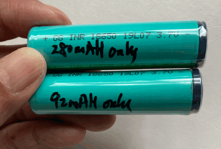
I tested all my batteries. Here is a photo of two batteries manufactured in 2019 that I salvaged from two portable USB blenders. Both batteries looks like brand new in apperance and does not have any information about battery capacity marked on the battery, so I don't know what was the original battery capacity. After running capacity test for the two batteries, one shows a capacity of merely 92mAh, and another has a battery capacity of 280mAh. Both end up in recycling bin.
Both the hardware schematic and software of my version of the Battery Capacity Tester are available on my github.