DS18B20 is a temperature sensor which communicates over a 1-Wire bus that by definition requires only one data line for communication with a host controller. I like DS18B20 as compare to other popular low cost temperature sensors for its accuracy and reliability. According to the DS18B20 data sheet, DS18B20 provides a digital Celsius temperature output with an accuracy of +/-0.5°C in the range of -10°C to +85°C.
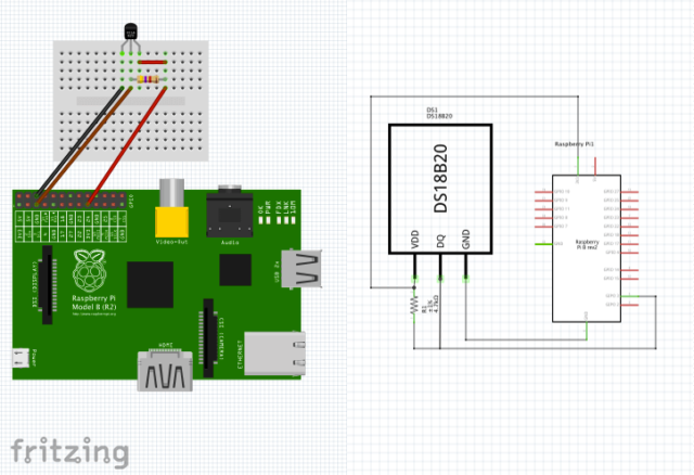
Connecting DS18B20 with Raspberry Pi
The DS18B20 that I purchased come as TO-92 package with 3 pins, I connect VDD to the 3.3V power source which is pin 1 on the Raspberry Pi GPIO header, GND to the GND of GPIO header pin 6. I'm going to use the GPIO4 (which is pin 7 on the Raspberry Pi GPIO header) as the data line connecting to DS18B20 DQ. A pull-up resister of 4.7kohm is required between DQ and VDD as shown in the circuit diagram. That's all the wiring required!
Enable 1-wire communication
There are many tutorials on the Internet about interfacing DS18B20 with Raspberry Pi. For most of the Raspberry Pi articles that were published before Jan 2015 (and for some throughout 2015), it is sort of obsoleted or no longer working since Raspberry Pi changed its kernels and firmware in early 2015 to use a Device Tree (DT) to manage some resource allocation and module loading. The detail of Raspberry Pi Device Tree implementation provided further information. The /boot/overlays/README in Raspbian serves as sort of official documentation on how to use the device tree overlay, and here is the part related to 1-wire GPIO
Name:   w1-gpio
Info:   Configures the w1-gpio Onewire interface module.
        Use this overlay if you *don't* need a GPIO to drive an external pullup.
Load:   dtoverlay=w1-gpio,=
Params: gpiopin                 GPIO for I/O (default "4")

        pullup                  Non-zero, "on", or "y" to enable the parasitic
                                power (2-wire, power-on-data) feature


Name:   w1-gpio-pullup
Info:   Configures the w1-gpio Onewire interface module.
        Use this overlay if you *do* need a GPIO to drive an external pullup.
Load:   dtoverlay=w1-gpio-pullup,=
Params: gpiopin                 GPIO for I/O (default "4")

        pullup                  Non-zero, "on", or "y" to enable the parasitic
                                power (2-wire, power-on-data) feature

        extpullup               GPIO for external pullup (default “5")
Based on this information, if I'm using GPIO4 as the data line, with a 3-wired Powered configuration, what I would need to add to the end of /boot/config.txt file would be as simple as:
dtoverlay=w1-gpio, pullup="on"
Although based on the /boot/overlays/README, the pullup="on" would only required when the DS18B20 operates in parasite powered mode, however, in my case, it will not working unless I added pullup="on", despite that I'm not configuring my DS18B20 to operate in parasite mode.
Save the /boot/config.txt and reboot the Raspberry Pi.
Temperature Reading from DS18B20
Login into Raspberry Pi, change to the device directory and list the file in the directory:
cd /sys/bus/w1/devices/28-000008284fb7/
ls
28-000008284fb7  w1_bus_master1
Each DS18B20 has a unique serial number which is shown as a 28-xxxxxxxxxxxx device directory. This is the ROM of DS18B20. If more than one DS18B20 are connected, there will be multiple directories named after each DS18B20 serial numbers.
To read the temperature, simple using linux command cat to get and display the data from w1_slave located within the DS18B20 ROM directory:
cd 28-00000284fb7
cat w1_slave
87 01 4b 46 7f ff 09 10 48 : crc=48 YES
87 01 4b 46 7f ff 09 10 48 t=24437
The number following t= divided by 1000 will be the temperature in Celcius, 24437 stands for 24.4 degree Celcius.
A Simple DS18B20 Data Logger without using Python
Any use of IoT (Internet of Things) devices involved Data Acquisition and Data Processing. DS18B20 temperature sensor as one kind of IoT devices is no exception. Most of the articles available online would talked about how to create a program using python to constantly display the temperature reading on screen (In fact, I suspected that many articles simply copy and paste someone's code into their article. What's fun of doing that?). In the world of IoT or sensors, the term of data acquisition means a process of collecting data and storing the data so that further measurement or analysis can be done whenever it is needed. So I'm going to create a data logger that will collect and log the data in a file automatically at regular interval.
First, let create a log file at /var/log/ which is a typical place for all the linux log files located.
sudo touch /var/log/ds18b20.log
sudo chown pi: /var/log/ds18b20.log
Create a shell script called ds18b20.sh at the home directory of the Raspberry Pi:
cd ~
nano ds18b20.sh
We can now write the script to get the temperature, create a timestamp after reading the temperature and append the timestamp and the temperature reading to the log. We don't need the entire temperature data get back from the w1_slave, in fact we only need the temperature reading which is the last 5 characters of the w1_slave reading, so we use shell command to trim the temperature reading with ${temp: -5}, and that's what we are going to append to the log file.
#!/bin/bash
temp=$(cat /sys/bus/w1/devices/28-000008284fb7/w1_slave)
timestamp=$(date +%Y-%m-%d_%H:%M:%S)
echo $timestamp' '${temp: -5} >> /var/log/ds18b20.log
Save the file and make the shell script that we just created executable:
sudo chmod +x ds18b20.sh
We can now test it by running the shell script:
~/ds18b20.sh
Check the log file by display the last record using tail command:
tail /var/log/ds18b20.log
2017-04-24_09:01:27 24437
Each record of the log only consists of 26 bytes, so if we log the data at an internal of 10 minutes, a yearly log file will be slightly less than 8.2MB (26 x 6 x 24 x 365 = 8,199,360 Bytes), so let's do that.
We will use the good old Linux utility crontab to carry out the automatic logging.
crontab -e
This will open a terminal editor with a new blank crontab file, or it will open an existing crontab that already have one. If you are first time running the command, it will prompt and asking to pick a text editor, press 2 or Enter for using nano editor.
Scroll down to the end of file and enter this line of script:
*/10 * * * * ~/ds18b20.sh
This tell the cron to run shell script ~/ds18b20.sh every 10 minutes.
Making a DS18B20 probe
So far I'm testing the circuitry and program on a breadboard, but I want to make it permanent so I solder the DS18B28 and the pull-up resistor to 3 cut-shorted jumper wires to make it like a "probe" as shown in the picture below.
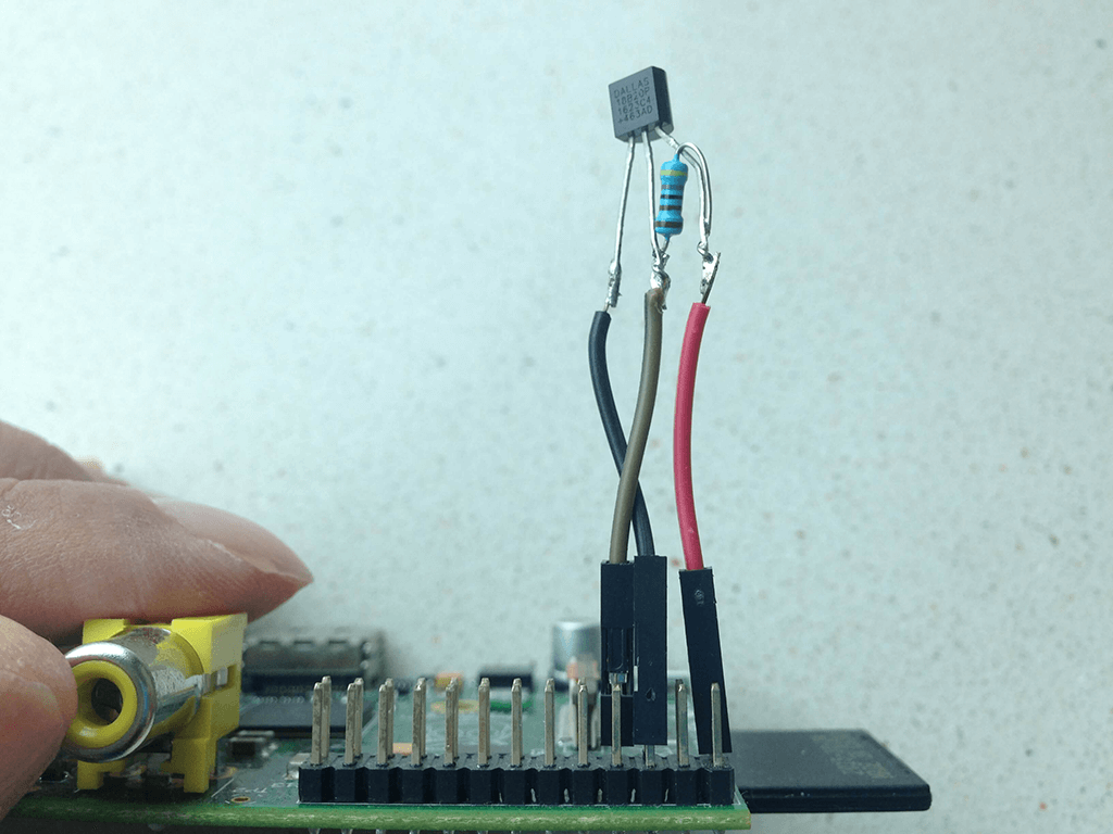
Update: It turns out that the probe is too short and too close to the Raspberry Pi and picked up the heat generated from the Raspberry Pi, I eventually have to extend the wires so that it is about 12-inch away from the Raspberry Pi.
Next step
That's all for now. I can take it further, for example, to plot data as a daily, weekly or month temperature chart, or create a RESTful web access API for getting the data, but that'll be another project and another article.
verry good working manual easy to understand and adapt for more sensors,
#!/bin/bash
temp=$(cat /sys/bus/w1/devices/28-00000a155004/w1_slave)
temp1=$(cat /sys/bus/w1/devices/28-00000a158a94/w1_slave)
temp2=$(cat /sys/bus/w1/devices/28-02151559e3ff/w1_slave)
temp3=$(cat /sys/bus/w1/devices/28-031504070aff/w1_slave)
timestamp=$(date +%Y-%m-%d_%H:%M:%S)
echo $timestamp' sensor1 '${temp: -5} ' sensor2 '${temp1: -5} ' sensor3 '${temp2: -5} ' sensor4 '${temp3: -5} >> /var/log/ds18b20.log
i had only 1 problem on the end because there was no editor selected on crontab so i had to set it manualy: